TM-9-2320-328-13-P-1 - Page 747 of 1318
TM 9-2320-328-13&P-1
0072-83
DRAFT
0072
Change 1
..
HWT2998
..
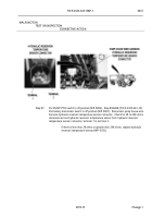
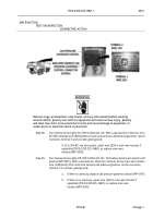
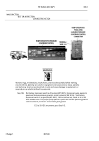
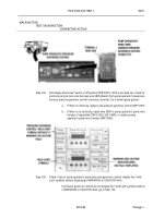
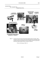
Step 101.
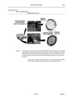
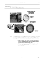
Pull battery disconnect switch to off position (WP 0007).
Disconnect main wire harness
pump operator’s panel 27-pin connector. Push battery disconnect switch to on
position (WP 0007).
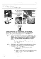
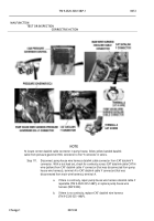
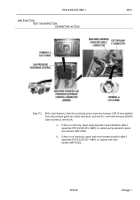
With a test lead set, check for 22 to 28 VDC between wire 1118
(red) at main wire harness pump operator’s panel 27-pin connector, terminal 9 to a
known good ground.
..
a.
If there is continuity, repair wire 1118 in pump operator’s panel wire
harness if repairable (TM 9-2320-325-14&P), or replace pump
operator’s panel wire harness (WP 0303).
..
b.
If there is no continuity, repair wire 1118 in main wire harness if
repairable (TM 9-2320-325-14&P), or replace main wire harness
(WP 0292).
..
HWT2708
..
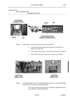
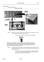
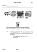
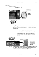
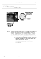
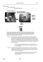
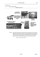
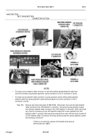
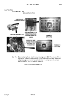
Step 102.
Turn Service Drive Lights On (TM 9-2320-422-10).
With a test lead set, check for 22 to
28 VDC between wire 2839 (white) at pump operator’s panel wire harness pressure
governor control connector, terminal 3 and a known good ground.
..
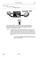
If 22 to 28 VDC are present, go to Step 104.
..
MALFUNCTION
TEST OR INSPECTION
CORRECTIVE ACTION
Back to Top

