TM-9-2320-328-13-P-2 - Page 667 of 1390
TM 9-2320-328-13&P-2
0204-11
DRAFT
0204
INSTALLATION
NOTE
•
Route wires as noted prior to removal.
•
Install cable ties, split loom, and cushion clips as required.
1.
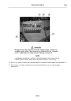
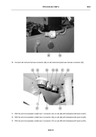
With the aid of an assistant, place cab instrument panel assembly (31) in vehicle.
2.
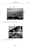
Remove five screws (29) from cab instrument panel B (30) and cab instrument panel assembly (31).
3.
Remove two screws (59) from cab instrument panel C (33) and cab instrument panel assembly (31).
4.
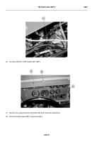
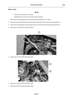
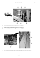
Repair wire 1412 (58) (TM 9-2320-325-14&P).
-
-
-
-
-
-
-
-
-
-
-
-
-
-
-
-
-
-
-
-
-
-
-
-
-
-
-
-
-
-
-
-
-
-
-
-
-
5.
Repair wire 1411 (57) (TM 9-2320-325-14&P).
-
-
-
-
-
-
-
-
-
-
-
-
-
-
-
-
-
-
-
-
-
-
-
-
-
-
-
-
-
-
-
-
-
-
-
-
-
6.
Repair wire 1020 (56) (TM 9-2320-325-14&P).
7.
Repair wire H012 (55) (TM 9-2320-325-14&P).
HWT2274A
HWT2273A
Back to Top

