TM-9-2320-346-10 - Page 150 of 1184
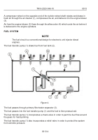
Remote-control unit (RCU) (2) can be operated from connectors located on the driver side
or passenger side of the vehicle.
NOTE
BAP is a special flatrack that contains a detachable winch frame assem-
bly.
When the BAP (3) is loaded and secured on the vehicle LHS (1), it serves as the base
support for interior or ramp bays during movement.
It provides a means to load and unload the interior ramp bays.
It also converts the LHS (1) into a ribbon bridge launch and retrieval arm.
The vehicle LHS (1) loads the BAP (3).
BAP winch (4) operation is possible only from the remote-control unit (2).
Electric power to operate the LHS (1) and BAP (2) is provided by a supply harness wired
into the HEMTT electrical system.
LHS MODE SELECT switch, remote-control unit switches, and electrical relays located in
the cab control box determine which individual function is activated.
Proximity switches mounted on the LHS permit simple load/unload operation of the LHS
when in the AUTO mode (cab controls only).
Hydraulic pressure is provided by a PTO-driven hydraulic pump located on the HEMTT
transmission.
LHS (1) hydraulics are connected to the HEMTT chassis via quick connect fittings.
Hydraulic pressure is controlled by relief valves and directional control valves. A vented
relief valve limits the maximum system pressure to 3,100 psi (21,374 kPa).
Winch circuit has tandem relief valves that limit pressure in the winch circuit to 2,100 psi
(14,479 kPa). Electrically-activated directional control valves control the flow of fluid to
individual components.
When no LHS (1) functions are being used, a free-flow valve vents the main relief valve,
which returns all fluid flow directly to the reservoir.
The moment a function is activated, the free-flow valve closes and pressurized oil is
delivered to the BAP winch (4) or LHS (1) hydraulic cylinders.
Counterbalance (holding) valves located in the hydraulic cylinder manifolds support the
payload whenever hydraulic pressure is not provided.
Transit valves in the main frame manifolds open during LHS (1) transit operations. This
relieves the system of hydraulic pressure and allows the payload to be supported by the
physical structure rather than the system hydraulics.
END OF WORK PACKAGE
TM 9-2320-346-10
0016
0016-2
Back to Top

