TM-9-2320-361-24-1 - Page 968 of 1176
TM 9-2320-361-24-1
0151 00
0151 00-4
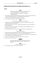
FORWARD-REAR AND REAR-REAR AXLE ASSEMBLY REPLACEMENT (Contd)
INSTALLATION
WARNING
Axle is heavy. Ensure axle is balanced and personnel are clear
before raising axle. Failure to do so may result in injury to
personnel.
NOTE
Assistant will help with step 1.
1.
Place hydraulic jack and axle under vehicle and position two axle spring seats (8) over ends of
spring (14).
2.
Raise hydraulic jack until springs (14) meet brackets (11) and align holes in axle spring seats (8)
with guide pins (10) on axle.
3.
Place two seats (9) in axle.
4.
Align two brackets (11) with axle spring seats (8) and install on axle with eight screws (16), two
brackets (15), eight new lockwashers (13), and nuts (12). Tighten nuts (12) 200–275 lb-ft
(271–373 N
•
m).
NOTE
Step 5 applies to left side.
5.
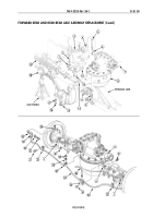
Align upper torque rod (1) and bracket (2) with plate (7) and install on axle with four screws (3),
two brackets (4), four new lockwashers (6), and nuts (5). Tighten nuts (5) 200–275 lb-ft
(271–373 N
•
m).
6.
Install tee (22) on bracket (4) with screw (21) and new locknut (18).
7.
Install hose (23) in tee (22).
8.
Install four new seal washers (30) and two hose connectors (31) on two wheel cylinders (17) with
two screws (29).
9.
Install brake line (20) and two clamps (19) on two brackets (15) with two screws (28) and new
locknuts (27).
10.
Install brake line (20) and clamp (24) on differential housing with washer (25) and nut (26).
Tighten nut (26) 53–76 lb-ft (72–103 N
•
m).
11.
Raise vehicle enough to move two jack stands from under tandem axle spring seats (14) to under
axle.
12.
Place jack stands under axle.
13.
Remove hydraulic jack from under vehicle.
14.
Install propeller shaft (as required) (WP 0139 00).
15.
Install inner and outer wheels (as required) (WP 0186 00).
16.
Bleed service brakes (WP 0172 00).
17.
Fill brake fluid to proper level (WP 0020 00).
18.
Connect battery ground cable (WP 0126 00).
19.
Release parking brake and remove wheel chocks (TM 9-2320-361-10).
Back to Top

