TM-9-2320-361-34 - Page 29 of 764
TM9-2320-361-34
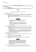
Table 2-1. Mechanical Troubleshooting (Contd).
MALFUNCTION
TEST OR INSPECTION
CORRECTIVE ACTION
17.
Step
5.
When a knocking noise is located at bottom of engine, remove oil pan (para.
3-11)
and check
condition of bearings, crankshaft, and rods for wear or defects.
a.
b.
c.
If bearings are worn or defective, replace engine (para. 3-18) and repair
(TM 9-2815-210-34-2-1 and -2-2).
If crankshaft or connecting rods are defective or damaged, replace engine (para. 3-18),
repair crankshaft or connecting rods (TM 9-2815-210-34-2-1 and -2-2).
If no defects are found, replace engine (para. 3-18). Remove pistons and rods and check
connecting rod wrist pins and pistons for wear or defects. Replace defective components
(TM 9-2815-210-34-2-1 and -2-2).
END OF TESTING!
ENGINE VIBRATION ABNORMAL
Step 1. Check for loose or defective vibration damper. Inspect vibration damper
(para. 3-4).
a. If vibration damper is loose, check woodruff key and crankshaft/vibration damper
mating surfaces for damages. Replace damaged components (para. 3-4).
b. If vibration damper is defective, replace (para. 3-4).
Step 2. Check for crossed fuel injector lines (para. 5-3).
If fuel injector lines are crossed, remove lines and install in correct locations (para. 5-3).
NOTE
If, after correctly installing crossed fuel injector lines, the engine
continues to vibrate excessively, pistons may have been burned
within engine combustion chambers. This condition cannot be
corrected unless affected piston(s) are replaced.
Step 3. Check engine cylinders compression readings (malfunction 11, steps 1 and 2).
Step 4. Complete troubleshooting malfunction 9.
END OF TESTING!
FUEL SYSTEM
●
Fuel is flammable. Do not perform troubleshooting checks near open
flame, sparks, or electricity. Injury to personnel may result.
. Eye protection is required when performing fuel system trouble-
shooting checks. Failure to wear eye protection may result in injury
to personnel.
. Ignition switch must remain off during fuel system troubleshooting
checks. Failure to verify that ignition system is turned off may result
in injury to personnel.
18.
NO FUEL AT FUEL INJECTORS
Step 1. Check fuel injection pump fuel shutoff operation and adjustment (TM 9-2815-210-34-2-1
and -2-2 or TM 9-2910-226-34). Place fuel shutoff cable control on instrument panel in RUN
position. Remove timing cover on fuel injection pump (para. 5-4). Visually inspect that fuel
shutoff clevis is tight against timing cover window bearing screw (para. 5-4).
2-14
Back to Top

