TM-9-2320-365-20-4 - Page 708 of 968
TM 9-2320-365-20-4
19-6. CAB HYDRAULIC LATCH REPLACEMENT/ADJUSTMENT
This task covers:
a. Removal
b. Installation
c. Adjustment
d. Follow-On Maintenance
INITIAL SETUP
Equipment Conditions
Engine shut down (TM 9-2320-365-10).
Cab raised (TM 9-2320-365-10).
Tools and Special Tools
Tool Kit, Genl Mech (Item 44, Appendix C)
Goggles, Industrial (Item 15, Appendix C)
Gloves, Rubber (Item 13, Appendix C)
Pan, Drain (Item 24, Appendix C)
Wrench, Torque, 0-175 lb-ft (Item 57, Appendix C)
Materials/Parts
Cap and Plug Set (Item 15, Appendix D)
Nut, Self-Locking (4) (Item 149, Appendix G)
Hydraulic Fluid A (Item 26, Appendix D)
a. Removal.
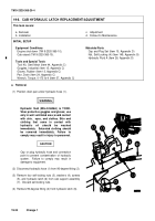
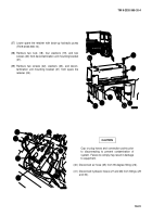
(1) Position drain pan under hydraulic hose (1).
WARNING
Hydraulic fluid (MIL-H-5606A) is TOXIC.
Wear protective goggles and gloves; use
only in well ventilated area; avoid contact
with skin,
eyes, and clothes. Skin and
clothing
that
come
in
contact
with
hydraulic
oil
should
be
washed
immediately.
Saturated clothing should
be
removed
immediately.
Failure
to
comply may result in injury to personnel.
CAUTION
Cap or plug hydraulic hose and connection
point to prevent contamination of hydraulic
system.
Failure to comply may result in
damage to equipment.
(2) Disconnect hydraulic hose (1) from 90-degree fitting (2).
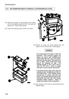
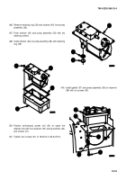
(3) Remove four self-locking nuts (3), washers (4), screws
(5), and hydraulic latch (6) from cab support assembly
(7). Discard self-locking nuts.
(4) Remove 90-degree fitting (2) from hydraulic latch (6).
19-24
Change 1
Back to Top

