TM-9-2320-365-34-1 - Page 36 of 1334
TM 9-2320-366-34-1
vi
Change 2
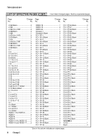
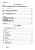
LIST OF ILLUSTRATIONS (CONT)
Figure
Title
Page
D-55
Front and Rear Differential Yoke Seal Driver
............................................................................................
D-67
D-56
Purge Valve Tool
..................................................................................................................................
D-69
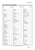
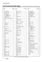
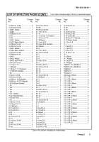
LIST OF TABLES
Number
Title
Page
2-1
Vehicle Troubleshooting
..........................................................................................................................
2-7
2-2
Engine System Fault Index
...................................................................................................................
2-13
2-3
Cooling System Fault Index
...................................................................................................................
2-65
2-4
Transmission System Fault Index
..........................................................................................................
2-73
2-4.1
C3 Pressure Switch
.............................................................................................................................
2-565
2-4.2
C3 Pressure Switch
.............................................................................................................................
2-579
2-4.3
C3 Pressure Switch
..........................................................................................................................
2-588.1
2-4.4
C3 Pressure Switch
.............................................................................................................................
2-943
2-4.5
C3 Pressure Switch
.............................................................................................................................
2-957
2-5
Wheel Fault Index
...............................................................................................................................
2-959
2-6
Hydraulic System Fault Index
...............................................................................................................
2-963
2-7
Steering Fault Index
.............................................................................................................................
2-969
2-8
11K Self-Recovery Winch (SRW) Fault Index
.........................................................................................
2-975
3-1
Crankshaft Positions for Valve Clearance Setting
....................................................................................
3-101
3-2
Valve Clearances
.................................................................................................................................
3-103
3-3
Valve Clearance Ranges
......................................................................................................................
3-103
4-1
Crankshaft Position
..............................................................................................................................
4-20
7-1
Torque Converter Shim Chart
.................................................................................................................
7-14
7-2
Torque Converter End Play Shim Chart
...................................................................................................
7-16
18-1
Support Leg Hole Location
...................................................................................................................
18-89
18-2
Power Distribution Panel Circuit Breakers
..............................................................................................
18-98
18-3
Terminal Lug Locations and Connectors
................................................................................................
18-99
20-1
Valve Specifications
.............................................................................................................................
20-12
20-2
Valve Spring Specifications
..................................................................................................................
20-13
20-3
Valve Seat Insert Specifications
............................................................................................................
20-14
20-4
Cylinder Head Surface Flatness
............................................................................................................
20-15
20-5
Crankshaft Main Bearing Journal Diameter
.............................................................................................
20-33
20-6
Crankshaft Connecting Rod Journal Diameter
.........................................................................................
20-33
20-7
Piston/Piston Ring Clearances
.............................................................................................................
20-45
20-8
Camshaft Minimum Lobe Lift
................................................................................................................
20-54
21-1
Selective Spacer Chart
.........................................................................................................................
21-12
23-1
Pinion Bearing Preload Chart
................................................................................................................
23-13
23-2
Pinion Cone Variation Chart
..................................................................................................................
23-16
24-1
Pinion Bearing Preload Chart
................................................................................................................
24-13
24-2
Pinion Cone Variation Chart
..................................................................................................................
24-16
D-1
Pneumatic Tube Lengths
.......................................................................................................................
D-56
D-2
Non-Metallic Electrical Cable Conduit Lengths
........................................................................................
D-58
E-1
Dry Torque Limits for SAE and ANSI Screws and Free Spinning Nuts
.........................................................
E-2
E-2
Dry Torque Limits for SAE and ANSI Prevailing Torque Nuts
.......................................................................
E-4
E-3
Dry Torque Limits for Metric Screws and Free Spinning Nuts
......................................................................
E-5
E-4
Dry Torque Limits for Metric Prevailing Torque Nuts
...................................................................................
E-6
E-5
Wet Torque Limits for SAE and ANSI Screws and Free Spinning Nuts
........................................................
E-7
Back to Top

