TM-9-2320-366-20-5 - Page 33 of 1158
TM 9-2320-366-20-5
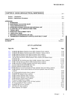
CHAPTER 24 GAGES (NON-ELECTRICAL) MAINTENANCE
..........................
24-1
Section I
Introduction
.........................................................
24-1
Section II
Maintenance Procedures
...............................................
24-2
APPENDIXES
A. REFERENCES
...............................................................
A
-1
B. MAINTENANCE ALLOCATION CHART
............................................
B
-1
C. TOOLS IDENTIFICATION LIST
..................................................
C
-1
D. EXPENDABLE/DURABLE SUPPLIES AND MATERIALS LIST
...........................
D
-1
E. ILLUSTRATED LIST OF MANUFACTURED ITEMS
....................................
E
-1
F. TORQUE LIMITS
.............................................................
F
-1
G. MANDATORY REPLACEMENT PARTS
............................................
G
-1
H. LUBRICATION ORDER
........................................................
H
-1
J. ADDITIONAL AUTHORIZATION LIST (AAL)
.........................................
J
-1
K. TRANSMISSION/TRANSMISSION CONTROLS ADAPTABILTY CHART
....................
K
-1
SUBJECT INDEX
.................................................................
Index-1
GLOSSARY
...................................................................
Glossary-1
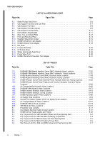
LIST OF ILLUSTRATIONS
Figure No.
Figure Title
Page
17-1.
M1084/M1086 Material Handling Crane (MHC) Hydraulic Hose Locations .
...............
17-20
17-2.
M1084/M1086 Material Handling Crane (MHC) Hydraulic Tubing Locations .
.............
17-32
17-3.
M1089 Material Handling Crane (MHC) Hydraulic Hose Locations .
....................
17-54
17-4.
M1089 Material Handling Crane (MHC) Hydraulic Tubing Locations .
...................
17-63
17-5.
15K Self-Recovery Winch (SRW) Hydraulic Hose Locations (All Models Except
M1090/M1094) .
........................................................
17-123
17-6.
M1090/M1094 15K Self-Recovery Winch (SRW) Hydraulic Hose Locations .
............
17-125
17-7.
M1089 15K Self-Recovery Winch (SRW) Hydraulic Hose Locations .
..................
17-129
17-8.
M1089 30K Winch Left/Right Hydraulic Hose and Tubing Locations .
..................
17-131
19-1.
Hydraulic Manifold PN HFC32598 Rear View .
...................................
19-11
19-1.1.
Hydraulic Manifold PN 65234 Rear View .
......................................
19-12
19-1.2.
M1089 Wrecker Control Panel External Power Hydraulic Hose and Tubing Locations .
......
19-25
19-2.
M1089 Wrecker Control Panel Pressure and Function Hydraulic Hose and Tubing
Locations .
.............................................................
19-26
19-3.
Air Transportability Hydraulic Hose Locations .
...................................
19-62
19-4.
M1090/M1094 Hydraulic Hose Locations .
......................................
19-71
19-5.
M1089 Underlift Hydraulic Hose Locations .
.....................................
19-74
19-6.
M1089 Underlift Hydraulic Tubing Locations .
....................................
19-79
19-7.
M1089 Hydraulic System Hose Locations .
......................................
19-89
23-1.
Primary Air Supply Hose Locations .
...........................................
23-3
23-2.
Central Tire Inflation System (CTIS) Air Hose Locations .
............................
23-5
23-3.
Air Transportability Air Hose Locations .
........................................
23-10
23-4.
M1090/M1094 Air Hose Locations .
...........................................
23-13
23-5.
30K Winch Air Hose Locations .
.............................................
23-15
E-1.
Brake Adjusting Tool Support .
................................................
E-5
Change 1
iii
Back to Top

