TM-9-2320-366-34-1 - Page 706 of 1591
Change 1
2-565
TM 9-2320-366-34-1
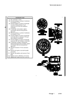
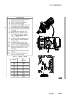
CONTINUITY TEST
(1)
Set multimeter to ohms.
(2)
Connect positive (+) probe of multimeter
to internal wiring harness 31-pin connector
pin X.
(3)
Connect negative (-) probe of multimeter
to internal wiring harness connector C3
pin B and note reading on multimeter.
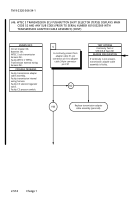
(4)
If continuity is not present, replace
transmission internal wiring harness
(para 7-13).
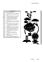
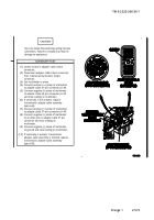
(5)
Connect positive (+) probe of multimeter
to internal wiring harness 31-pin connector
pin X.
(6)
Connect negative (-) probe of multimeter
to all other pins in internal wiring harness
31-pin connector and note reading on
multimeter.
(7)
Connect negative (-) probe of multimeter
to ground and note reading on multimeter.
(8)
If continuity is present, transmission
internal wiring harness is shorted; replace
transmission internal wiring harness
(para 7-13).
(9)
Connect internal wiring harness
connector C3 to C3 pressure switch
connector.
(10)
Install cover on control valve module
with four screws.
(11)
Install control valve module (para 7-10).
(12)
Connect batteries (TM 9-2320-366-20-3).
Back to Top


