TM-9-2320-386-24-1-1 - Page 525 of 1078
0139 00-2
TM 9-2320-386-24-1-1
0139 00
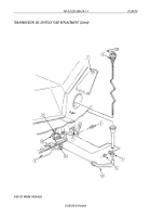
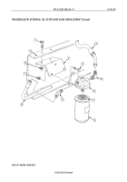
TRANSMISSION OIL COOLER HOSES REPLACEMENT (Contd)
REMOVAL
1.
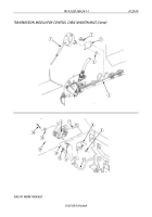
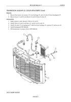
Remove tiedown straps (24), as required. Discard tiedown straps (24).
2.
Remove locknuts (15), screws (12), and clamps (13) from hose (14) and frame (18) as required.
Discard locknuts (15).
3.
Remove three screws (6) and clamps (7) from supply hose (5) and fender (26).
WARNING
Accidental or intentional introduction of liquid contaminants into
the environment is in violation of state, federal, and military
regulations. Refer to Army POL (WP 0001 00) for information
concerning storage, use and disposal of these liquids. Failure to do
so may result in injury or death.
Transmission oil may be hot when it is drained from the
transmission oil cooler. Use caution when disconnecting supply
hoses. Failure to do so may cause injury to personnel.
NOTE
Have drainage container ready to catch oil.
4.
Disconnect supply hose (5) and return hose (25) from adapter (4) and elbow (2) on transmission (30).
NOTE
Note position of elbows for installation.
If oil is leaking at elbows, perform steps 5 and 6.
5.
Remove pipe tee (3) from elbow (2).
6.
Remove two elbows (2) and O-rings (1) from transmission (30). Discard O-ring (1).
7.
Disconnect supply hose (5) from elbow (10) on radiator (11).
8.
Disconnect hose (14) and return hose (25) from elbows (16) and (19) on oil filter base (17).
9.
Remove locknut (8), screw (21), and clamps (22) and (23) from return hose (25), brake line (20), and
frame (18). Discard locknut (8).
10.
Remove screw (29), lockwasher (28), and clamp (27)
from return hose (25) and transmission (30).
Discard lockwasher (28).
11.
Disconnect hose (31) from elbow (32) on auxiliary oil cooler (33) and elbow (9) if not removed with
brushguard.
INSTALLATION
1.
Apply sealant to male threads of adapter (4) and elbows (10), (16), (19), and (32).
2.
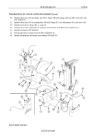
Connect return hose (25) and hose (14) to elbows (16) and (19) on oil filter base (17).
3.
Connect supply hose (5) to elbow (10) on radiator (11).
NOTE
If removal steps 5 and 6 were performed, perform steps 4
through 6.
4.
Apply sealant to male threads of pipe tee (3) and two elbows (2).
5.
Install pipe tee (3) on elbow (2).
6.
Install two new O-rings (1) and elbows (2) on transmission (30).
7.
Route supply hose (5) and return hose (25) to transmission (30) and install on adapter (4) and
elbow (2).
8.
Install hose (14) on frame (18) with clamps (13), screws (12), and new locknuts (15) as required.
9.
Install supply hose (5) on fender (26) with three clamps (7) and screws (6).
Back to Top

