TM-9-2320-386-24-1-1 - Page 587 of 1078
TM 9-2320-386-24-1-1
0157 00
AIR-HYDRAULIC BOOSTER REPLACEMENT (Contd)
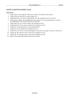
INSTALLATION
1.
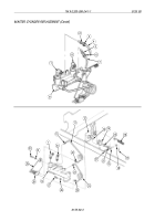
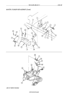
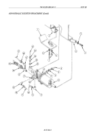
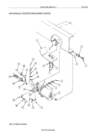
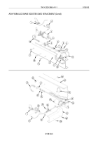
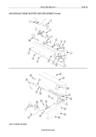
Apply antiseize tape to male threads of stoplight switch (23), tee (22), elbows (14), (19), and (27),
and adapters (10) and (30).
2.
Install tee (22) on air-hydraulic booster (13).
3.
Install stoplight switch (23) on tee (22).
4.
Install elbow (19) on port (21).
5.
Install elbow (14) on port (20).
6.
Install elbow (27) on tee (22).
8.
Install new gasket (11) and adapter (10) on port (12).
7.
Install new gasket (29) and adapter (30) on port (28).
9.
Install air-hydraulic booster (13) on mounting bracket (5) with new lockwasher (3) and screw (4).
10.
Install one screw (7) to support air-hydraulic booster (13) on mounting bracket (2).
11.
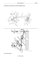
Install tube (32) on adapter (30) with nut (31).
12.
Install tube (25) on elbow (27) with nut (26).
13.
Install tube (8) on adapter (10) with nut (9).
14.
Install tube (16) on elbow (14) with nut (15).
15.
Install tube (17) on elbow (19) with nut (18).
16.
Remove screw (7) and install air-hydraulic booster (13) and skid plate (1) on mounting bracket (2)
with two screws (7) and new lockwashers (6).
17.
Install two leads 75 (24) on stoplight switch (23).
18.
Bleed service brakes (WP 0154 00).
19.
Start engine (TM 9-2320-386-10) and allow air pressure to build and check system for leaks.
0157 00-4
Back to Top

