TM-9-2320-386-24-1-1 - Page 984 of 1078
INSTALLATION
1.
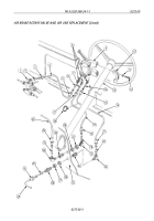
Apply adhesive to male threads of elbows (16), (33), (38), and (43), unions (12) and (24), and tee (35).
2.
Install air lines (7) and (27), with inserts (23) and (25), on union (24) and tighten nuts (22) and (26).
3.
Install air lines (9) and (15), with inserts (11) and (13), on union (12) and tighten nuts (10) and (14).
4.
Install elbow (16) on check valve (17).
5.
Install air line (20), with insert (18), on elbow (16) and tighten nut (19).
6.
Install elbow (33) on pressure switch (45).
7.
Install pressure switch (45) on crossmember (4) with two screws (34), washers (5), and new
locknuts (6).
8.
Install tee (35) on check valve (42).
9.
Install elbows (38) and (43) on check valve (42).
10.
Install check valve (42) on crossmember (4) with screw (41) and new locknut (39).
11.
Install air line (30), with insert (32), on elbow (33) and tighten nut (31).
12.
Install air lines (9), (30), (7), and (2), with inserts (36), (28), (40), and (44), on tee (35) and elbows (38)
and (43) and tighten nuts (37), (29), (8), and (3).
13.
Install four new tiedown straps (21) on air lines (30), (20), (9), (7), and (2).
14.
Connect two leads 75 (46) of air brake electrical harness (1) to pressure switch (45).
0275 00-4
TM 9-2320-386-24-1-1
0275 00
AIR BRAKE CHECK VALVE, PRESSURE SWITCH, AND AIR LINE REPLACEMENT (Contd)
Back to Top

