TM-9-2320-386-24-1-2 - Page 510 of 636
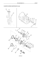
INSTALLATION
1.
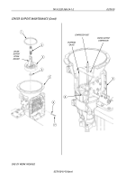
Install center support lifting bracket on center support assembly (3).
2.
Align threaded anchor bolt hole with hole in transmission (5) and install thrust washer (4), if not
already installed, and center support assembly (3) in transmission (5).
3.
Remove center support lifting bracket from center support (3).
4.
Install washer (6) and screw (7) on transmission (5). Finger-tighten screw (7).
5.
Install center support compressor on transmission (5) and center support assembly (3) with two
mounting screws. Tighten compressor bolt 5 lb-ft (7 N
•
m).
NOTE
Snapring gauge has four lugs of different thicknesses. The
thickness of the lug which will enter snapring groove indicates the
thickness of snapring to be used. Use all four lugs in snapring
groove.
6.
Using snapring gauge, measure thickness of snapring groove (8). Refer to table 1, Center Support
Snapring Thickness, for measurement.
Table 1. Center Support Snapring Thickness.
7.
Install snapring (1) in snapring groove (8) of transmission (5). Gap of snapring (1) must be at
12 o’clock position at top of transmission (5).
8.
Remove two mounting screws and center support compressor from transmission (5).
9.
Tighten screw (7) 39-46 lb-ft (53-62 N
•
m).
10.
Install sun gear shaft (2), with long spline in downward position, in transmission (5).
11.
Install third clutch (WP 0377 00).
12.
Install transmission control valve (WP 0371 00).
0.149
3.78
Blue
0.148-0.150
3.76-3.81
0.153
3.89
Yellow
0.152-0.154
3.86-3.91
0.156
3.96
Green
0.155-0.157
3.94-3.99
0.159
4.04
Red
0.158-0.160
4.01-4.06
GAUGE THICKNESS
SNAPRING COLOR
SNAPRING THICKNESS
IN.
MM
CODE
IN.
MM
0378 00-8
TM 9-2320-386-24-1-2
0378 00
CENTER SUPPORT MAINTENANCE (Contd)
Back to Top


