TM-9-2320-431-10-1 - Page 159 of 1244
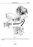
A belt-driven 24 VDC alternator (4) having a capacity of 65 amps (M983 - 100 amps) or 130
amps maintains the charge on the batteries.
The AMPERES gauge (5) shows the alternator output.
The BATTERY gauge (6) shows the state of charge of the batteries and alternator voltage
output.
The vehicle electrical circuits are protected against overloads by automatic reset circuit
breakers (7) located below the heater compartment panel.
MAJOR ELECTRICAL SYSTEM COMPONENT LOCATION
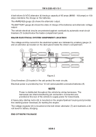
The voltage and the current for the electrical system are indicated by a battery gauge (1)
and an ammeter (2) located on the dash panel inside the driver's compartment.
2
1
7
6
5
3
4
Figure 2.
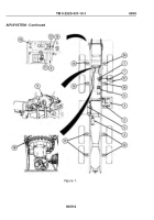
Circuit breakers (3) located in the cab protect the main circuits.
Electrical power is provided by four 12-volt series-parallel connected batteries (4).
NOTE
Power is distributed throughout the vehicle by wiring harnesses. The
harnesses are interconnected by pin connectors. Connectors are
provided at the rear of the vehicle to supply power for towed loads.
A heavy-duty starting motor (5) is mounted on the engine flywheel housing and provides
the cranking power necessary for starting the engine.
The voltage regulator (6) is mounted on the belt driven alternator (7) and maintains a 24-
volt level for battery charging.
END OF WORK PACKAGE
TM 9-2320-431-10-1
0008
0008-3
Back to Top


