TM-9-2330-267-14-P - Page 122 of 354
TM 9-2330-267-14&P
4-39. AIRBRAKE CHAMBER REPLACEMENT.
This Task Covers:
a.
Test
c.
Installation
b. Removal
Initial Setup:
Materials/Parts:
Tools/Test Equipment:
l Three Iockwashers
l General mechanic’s tool kit
Personnel Required: Two
1.
2.
3.
4.
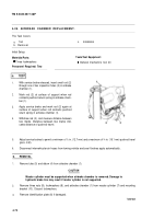
With service brake released, insert small rod (2)
through one of two inspection holes (3) in airbrake
chamber (1).
Mark rod (2) at surface of support when rod
contacts pushrod return spring in airbrake cham-
ber (1).
Apply service brake and mark rod (2) again at
surface of support when rod contacts pushrod
return spring in airbrake chamber (1).
Withdraw rod (2), and measure distance between
two marks. Distance between two marks indi-
cates distance of pushrod travel.
5.
Adjust service brakes to permit a minimum of ½ in. (12.7 mm) and a maximum of ¾ in. (19.1 mm) pushrod travel
(para 4-32).
6.
Disconnect intervehicular air hoses from towing vehicle and see if brakes apply automatically.
b.
REMOVAL
1.
Remove tube (5) and elbow (4) from airbrake chamber (1).
CAUTION
Master cylinder must be supported when airbrake chamber is removed. Damage to
hydraulic brake line may result if master cylinder is not supported.
2.
Remove three nuts (9), Iockwashers (8), and airbrake chamber (1) from master cylinder (7) and mounting
bracket (10). Discard Iockwashers.
3.
Remove identification plate (6) if damaged.
TA507038
4-72
Back to Top


