TM-9-2350-238-10 - Page 27 of 291
TM 9-2350-238-10
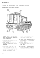
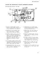
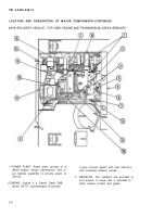
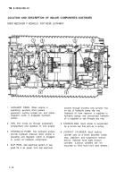
LOCATION AND DESCRIPTION OF MAJOR COMPONENTS–CONTINUED
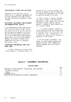
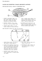
M578 RECOVERY VEHICLE– DRIVER ‘S COMPARTMENT VIEW
1
2
3
DRIVER’S INSTRUMENT PANEL. This
driver to energize various systems in the
panel contains gauges and lights that
vehicle, including hydraulic functions. A
allow driver to observe vital engine,
speedometer and tachometer allow obser-
transmission and electrical functions.
vation of vehicle and engine speed,
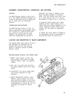
DRIVER’S CONTROLS. These controls
4 GAS-PARTICULATE FILTER UNIT. This
allow driver to drive and operate vehicle.
filter unit provides protection for driver
against toxic gases (except carbon monox-
DRIVER’S SWITCH PANEL. This panel
ide) and extremely dusty conditions.
contains switches and controls that allow
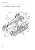
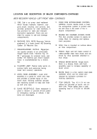
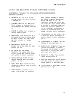
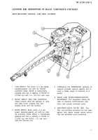
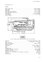
M578 RECOVERY VEHICLE–TOP VIEW, HULL BOTTOM
1
2
3
ENGINE DRAIN COVER. This cover pro-
4 FUEL PLUGS. These two plugs are re-
vides access for draining engine oil,
moved to drain fuel cell.
POWER PLANT RESERVOIR DRAIN PLUG.
5 TRANSMISSION DRAIN COVER. This
This plug is installed during fording opera-
cover provides access for draining
tions to prevent flooding of power plant
transmission oil.
reservoir. The plug should be wired to
hand throttle control rod in the driver’s
compartment during normal operations.
RADIATOR DRAIN COVERS, These two
covers provide
from radiator.
1-12
access for draining coolant
Back to Top

