TM-9-2350-238-20-1 - Page 1294 of 1364
TM 9-2350-238-20-1
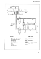
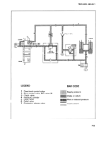
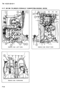
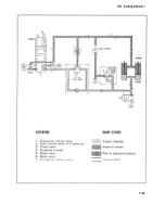
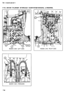
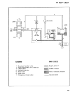
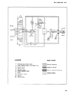
F-15. BOOM CYLINDER HYDRAULIC SUBSYSTEM.
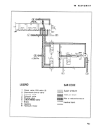
functional Description.
a.
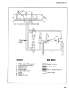
The hydraulic fluid power for the
d.
Moving the handle of the directional
operation of the boom cylinders is supplied
control valve ( 1 ) in the LOWER position
by the hydraulic power subsystem.
directs hydraulic fluid to the retract ports of
the boom cylinders (4), which
lowers the
b.
The boom cylinder hydraulic sub-
boom. The relief valve (6) protects the sub-
system controls the power to raise and
system from overpressure. Hydraulic
lower the boom.
pressure passing through the flow control
valve (2) causes the relief valve (5) to open
c.
Moving the handle of the directional
and allow return flow to the reservoir.
control valve ( 1 ) in the RAISE position
directs hydraulic fluid through the bypass
e.
When the handle of the directional
check valve of the relief valve (5) to the
control valve (1) is in the neutral position,
extend ports of the boom cylinders (4),
hydraulic fluid is blocked, hydraulically lock-
which raises the boom. The relief valve (6)
ing the boom cylinders in a fixed position.
releases excess hydraulic fluid pressure
The emergency release valve (7) can be
over 2150 psi (14,824 kPa) to return to
opened to lower the boom.
the reservoir.
F-30
Back to Top

