TM-9-2350-238-20-1 - Page 1308 of 1364
TM 9-2350-238-20-1
F-22. IMPACT WRENCH HYDRAULIC SUBSYSTEM.
Functional Description.
a.
Hydraulic fluid power for the opera-
tion of the impact wrench is supplied by
the 8 gpm pump of the hydraulic power
subsystem.
b.
The impact wrench hydraulic sub-
system is a continuous flow system, which
allows return fluid from the impact wrench
to continue on to the spade hydraulic sub-
system, During impact wrench operation,
the impact wrench is connected to the flow
control manifold by means of flexible hoses
and quick-disconnect couplings.
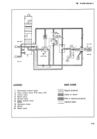
c.
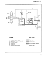
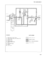
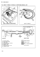
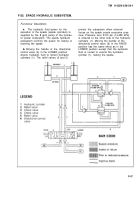
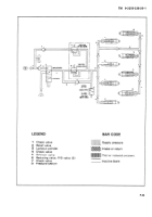
Pulling out the two-way valve (1)
allows hydraulic fluid to flow through the
flow control valve (2), through quick-
disconnects (4) and the extension hose (5),
and on to the impact wrench. Then by
pressing the control trigger of the selector
valve (6), hydraulic fluid passes through the
directional control valve (7) to the hydraulic
motor (8). The hydraulic motor (8) rotates
in either a clockwise or counterclockwise
direction, depending upon the setting of the
directional control valve (7). The speed of
the hydraulic motor (8) is controlled by ad-
justing the flow control valve (2).
F-44
Back to Top

