TM-9-2350-238-20-2 - Page 449 of 495
TM 9-2350-238-20- 2
F-15. BOOM CYLINDER HYDRAULIC SUBSYSTEM .
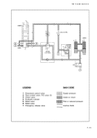
Functional Description .
a.
The hydraulic fluid power for th e
d.
Moving the handle of the directiona l
operation of the boom cylinders is supplie d
control valve (1) in the LOWER positio n
by the hydraulic power subsystem .
directs hydraulic fluid to the retract ports o f
the boom cylinders (4), which lowers th e
b.
The boom cylinder hydraulic sub -
boom. The relief valve (6) protects the sub-
system controls the power to raise an d
system from overpressure. Hydrauli c
lower the boom .
pressure passing through the flow contro l
valve (2) causes the relief valve (5) to ope n
c .
Moving the handle of the directiona l
and allow return flow to the reservoir .
control valve (1) in the RAISE positio n
directs hydraulic fluid through the bypass
e.
When the handle of the directiona l
check valve of the relief valve (5) to th e
control valve (1) is in the neutral position ,
extend ports of the boom cylinders (4) ,
hydraulic fluid is blocked, hydraulically lock-
which raises the boom. The relief valve (6)
ing the boom cylinders in a fixed position .
releases excess hydraulic fluid pressur e
The emergency release valve (7) can b e
over
2150
psi
(14,824
kPa)
to
return
to
opened to lower the boom .
the reservoir .
F-3 0
Back to Top


