TM-9-2350-238-20-2 - Page 471 of 495
TM 9-2350-238-20- 2
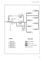
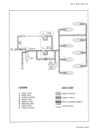
F-28. SUSPENSION LOCKOUT HYDRAULIC SUBSYSTEM .
Functional Description .
a .
The suspension lockout hydrauli c
one side of the cylinder piston to the other .
subsystem forms a hydrostatic lock withi n
The pressure switch (8) is closed whe n
each lockout cylinder (3). This stops up an d
pressure in the lockout cylinder is over 12 0
down movement of the road wheels an d
psi (827 kPa), lighting the SUSPENSION
provides a solid hoisting platform .
LOCKED indicator lights. When the hydrau-
lic pressure drops below 95 psi (655 kPa) ,
b.
Lockout cylinders (3) are locked b y
the pressure switch (8) opens, putting ou t
setting the selector control valve (5) t o
the SUSPENSION LOCKED indicator lights .
LOCKED. Hydraulic fluid at 1600 to 240 0
psi (11,032 to 16,548 kPa) flows throug h
c.
The subsystem is protected fro m
the valve (5) to the valve (6). The valve (6)
overpressure by the relief valve (2), whic h
reduces the fluid pressure to 150 psi (103 4
bypasses fluid over 240 psi (1655 kPa)
kPa). As the fluid pressure builds up in th e
back to the reservoir. The cylinders (3) ar e
lockout cylinders (3), the lockout pistons
unlocked by setting the valve (5) t o
are forced into the lockout position. This
UNLOCKED. This allows the hydraulic flui d
prevents hydraulic fluid from passing fro m
to flow back to the reservoir .
F-5 2
Back to Top


