TM-9-2350-256-10 - Page 88 of 796
DESCRIPTION AND USE OF OPERATOR'S CONTROLS AND INDICATORS - Continued
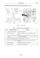
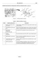
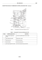
Figure 11.
Winches and Boom Controls.
Table 11. Winches and Boom Controls.
ITEM
CONTROL/INDICATOR
FUNCTION
1
SPADE bi-directional control
valve handle
Used to RAISE, LOWER, and HOLD spade. Spring loaded to stay
in HOLD position.
2
SYSTEM SELECTOR control
lever
Selects between MAIN hydraulic system, auxiliary (AUX) hydraulic
system or refuel/defuel (REFUEL), and impact wrench operations.
3
MAIN WINCH
bi-directional
control valve handle
Controls PAYOUT and INHAUL motion of main winch cable.
4
POWER
control lever
Turns main hydraulic pump ON or OFF. Locks in desired position.
5
BOOM SAFETY control lever
Used in conjunction with BOOM operating lever to raise/lower
boom from STOW position.
6
HOIST WINCH bi-directional
control valve handle
Controls LOWER and RAISE motion and HOLD function of hoist
winch cable.
7
BOOM operating lever
Controls FORWARD and RETRACT motion of boom when in live
boom position. Controls deploy and STOW motion of boom in
conjunction with BOOM SAFETY directional control valve.
TM 9-2350-256-10
0004
0004-14
Back to Top

