TM-9-2350-256-20-1 - Page 680 of 948
TM 9-2350-256-20-1
0097 00
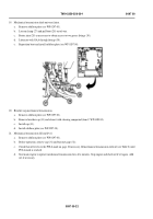
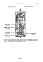
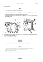
5.
Brake slack adjuster lever.
a.
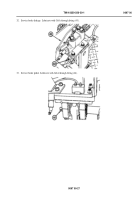
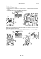
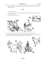
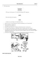
Remove six screws (8) and six lockwashers (9) which secure brake adjustment access cover (10) to bottom of hull.
b.
Remove access cover (10) and gasket (11).
c.
Lubricate brake slack adjuster lever with GAA through fitting (12).
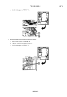
d.
Install gasket (11), access cover (10), six screws (8), and lockwashers (9). Repeat procedure for other side of vehicle.
6.
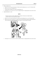
Output reduction drives—drain.
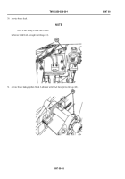
NOTE
Each time transmission is drained, approximately five gallons of oil remain in each output reduction
assembly. Drain oil each time transmission is flushed.
a.
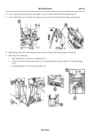
Remove six screws (8) and six lockwashers (9) which secure brake adjustment access cover to bottom of hull.
b.
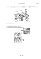
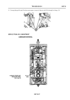
Remove access cover (10) and gasket (11). Remove bolt (13) located at bottom centerline of saddle mounting face
(this is the same bolt that secures end of brake stop to assembly). After oil has drained, install bolt.
Back to Top

