TM-9-2350-256-34 - Page 181 of 584
TM 9-2350-256-34
0032 00
INTERMEDIATE MAINTENANCE
RECOVERY VEHICLE, FULL TRACKED: MEDIUM, M88A1
NSN 2350-00-122-6826, EIC AQA
ENGINE
COOLING
FANS
MAINTENANCE
DESCRIPTION, REMOVAL, DISASSEMBLY, ASSEMBLY, INSTALLATION
INITIAL SETUP:
Tools and Special Tools
Tool kit, general mechanic’s (item 34, WP 0086 00)
Materials/Parts
Bolts (32) (item 41, WP 0087 00)
Nuts (32) (item 175, WP 0087 00)
Materials/Parts (cont.)
Pins, cotter (32) (item 113, WP 0087 00)
Washers (32) (item 21, WP 0087 00)
References
TM 9-2350-256-20
DESCRIPTION
The engine cooling fans are attached to hubs and are mounted on shafts that are driven by the engine-driven fan drive clutch
assembly. The hub and fan assemblies are balanced, but each assembly can be replaced without affecting the balance of the
complete unit. Both hub and fan assemblies are interchangeable.
Removal
1.
Remove engine cooling fans in accordance with TM 9-2350-256-20.
Disassembly
NOTE
Both the forward and rear cooling fans are disassembled the same way. This procedure covers one
cooling fan.
1.
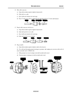
Remove 16 cotter pins (1), nuts (2), bolts (3), washers (4), hub body (5), and fan impeller (6). Discard cotter pins.
0032 00-1
Back to Top

