TM-9-2350-256-34 - Page 476 of 584
TM 9-2350-256-34
0083 00
7.
Check the pressure gage to confirm a hydraulic load on the auxiliary pump of 2000 ± 50 psi (13,790 ± 345 kPa). Ifnecessary,
adjust the system selector valve relief valve with the adjusting screw to obtain a pressure reading of 2000 ± 50 psi (13,790 ±
345 kPa). Check engine rpm for 2000 ± 100 rpm. If engine rpm is below 2000 ± 100 rpm, troubleshoot.
8.
Continue to operate the auxiliary engine for 10 minutes with a 2000 ± 50 psi (13,790 ± 345 kPa) load on the auxiliary
hydraulic pump and no load on the generator.
9.
Check all points for leakage in accordance with TM 9-2350-256-20 and correct any other defects. Return system selector
valve to MAIN position and shut off engine.
10.
Calibrate the current limiter in accordance with TM 9-2350-256-20. With the load as specified, verify that the engine speed
remains within 2000 ± 100 rpm. If not, readjust the governor speed control. If the engine cannot maintain 2000 ± 100 rpm
under generator load, troubleshoot.
Installation
1.
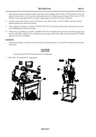
Attach sling to lifting eye and remove four lockwashers (24), mounting bolts (25), and APU (23) from test stand. Discard
lockwashers.
CAUTION
Carefully guide APU (23) into proper position in compartment.
3.
Move APU (23) into position in compartment.
0083 00-24
Back to Top


