TM-9-2350-277-20-2 - Page 579 of 783
TM 9--2350--277--20--2
0231 01--2
REPL ACE VARI ABL E SPEED FAN DRI VE VALVE AND O VERRI DE SW I T CH (NEW
CONFIGURATION) -- Continued
0231 01
9.
Remove fitting (19) and packing (20) from power plant (4). Discard packing.
Change 2
REMOVAL
1.
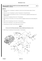
Remove two screws (1), lockwashers (2), and bracket (3) (with valve and switch) from power plant (4). Discard
lockwashers.
2.
Remove two screws (5), lockwashers (6), and valve (7) from bracket (3). Discard lockwashers.
3.
Remove oil supply hose (8) from elbow (9) on valve (7). Cover hose end with any appropriate material to prevent oil
leaking from hose.
4.
Remove elbow (9) and packing (10) from valve (7). Discard packing.
5.
Remove lube hose (11) from elbow (12). Cover hose end with any appropriate material to prevent oil from leaking from
hose.
6.
Remove elbow (12) and packing (13) from valve (7). Discard packing.
7.
Remove nut (14), lockwashers (15), and override switch (16) from bracket (3).
8.
Tag and disconnect two leads (17) and (18) from override switch (16).
NOTE
Perform step 9 only if fitting and packing are leaking and tightening the fitting does not work.
Back to Top

