TM-9-2350-277-20-4 - Page 422 of 861
TM 9-2350-277-20-4
ADJUST RAMP LOCK (M577A3 AND M1068A3 ONLY) — Continued
0522 00
6.
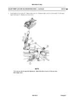
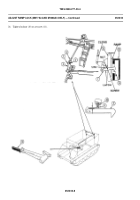
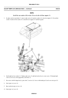
Loosen locknuts (1) on both sides of the vehicle.
CAUTION
Insure proper thread engagement after clevis adjustment. Thread engagement should be at
least 1-1/2 times diameter of rod.
NOTE
Setscrew must be adjusted so the center of the top arm is offset toward front of vehicle in
reference to the center of rod.
7.
Adjust two setscrews (2) and rotate arm (3) until center line of arm (3) is aligned with center line of rod (4). Continue to
rotate arm (3) until it is tilted 1/8 inch (3 mm) past center in reference to rod (4) toward front of vehicle.
8.
Tighten locknut (1) on setscrew (2).
0522 00-3
Back to Top


