TM-9-2350-277-20-5 - Page 304 of 1047
TM 9-2350-277-20-5
REPAIR PERSONNEL HEATER CONTROL BOX — Continued
0702 00
ASSEMBLY
NOTE
Before connecting electrical leads, check tags and wiring diagram below to verify proper
connection.
NOTE
Make sure key in receptacle is at the top.
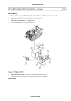
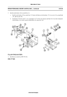
1.
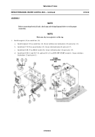
Install receptacle (13) in control box (14).
a.
Install receptacle (13) in control box (14). Secure with four new lockwashers (12) and screws (11).
b.
Install lead 17-D (9) on circuit breaker (10). Secure with lockwasher (8) and screw (7).
c.
Install lead 12-B (17) on HI-LO switch (18). Secure with lockwasher (16) and screw (15).
d.
Install lead 19-E (5), lead 20-C (4), and lead 14-A (3) on RUN-OFF-START switch (6). Secure with three
lockwashers (2) and screws (1).
0702 00-5
Back to Top

