TM-9-2350-311-10 - Page 49 of 775
TM 9-2350-311-10
1-11
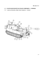
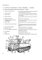
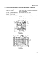
LOCATION AND DESCRIPTION OF MAJOR COMPONENTS - CONTINUED
1-11.2
Location and Description of Major Internal Hull Components
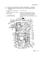
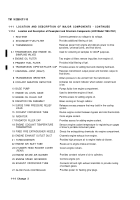
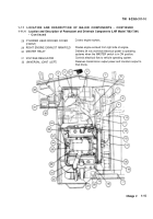
1 COOLANT SURGE TANK
2
FUEL TANK AND PUMPS
3
AIR CLEANER
4
PERSONNEL HEATER
5
FIXED FIRE EXTINGUISHER
6
CANISTER STOWAGE
7
8
9
10
11
12
13
PROJECTILE RACKS
ACCESSORY CONTROL BOX
DRIVER’S SEAT ASSEMBLY
PORTABLE AND DRIVER’S
INSTRUMENT PANELS
DRIVER’S CONTROLS
M2A2 AIR PURIFIER (M109A4/M109A5)
BATTERY
Has a capacity with the radiator of holding 22 gallons (83 I) of
coolant.
Allows fuel to be distributed to engine and stored.
Filters impurities from air before it reaches engine.
Provides heated air to driver’s and crew compartments.
Two fixed fire extinguishers allow for extinguishing of fire in the
engine compartment.
Provides stowage of 21 to 22 mixed canisters on left and right
sponson compartments and hull floor.
Provide stowage for 12 rounds on hull floor.
Controls operation of personnel heater, ventilation fans, and
lead filters.
Provides seating for driver.
Provides driver with instruments and switches to operate ve-
hicle.
Provides driver with controls to operate the vehicle.
Provides filtered air to the M3 electrical heaters.
Four batteries are contained in vehicle.
Change 2
1-11
Back to Top

