TM-9-2350-311-20-1 - Page 43 of 1275
TM 9-2350-311-20-1
1-17.7.2
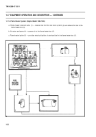
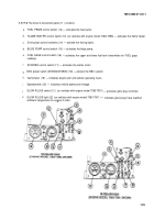
The driver’s instrument panel (11 ) contains:
a.
b.
c.
d.
e.
f.
g..
h.
i.
j.
k.
FUEL PRIME control switch (12) — activates the fuel pump.
FLAME HEATER control switch (13) (on vehicles with engine model 7083-7396) — activates the flame heater.
Driving light control switches (14) — activate the driving lights.
BILGE PUMP control switch (15) — activates the bilge pump.
FUEL GAGE control switch (16) — activates the upper and lower fuel tank transmitters for FUEL gage
readings.
STARTER control switch (17) — activates the starter motor.
NBC power switch (M109A4/M109A5) (18) — powers the NBC system.
Tachometer (19) — indicates engine rpm and vehicle operating hours.
Speedometer (20) — indicates vehicle speed and mileage.
GLOW PLUGS switch (21 ) (on vehicles with engine model 7083-7391)
— activates glow plug controller.
GLOW PLUGS light (22) (on vehicles with engine model 7083-7391 ) —
indicates glow plugs have reached
sufficient temperature for engine to start.
1-29
Back to Top

