TM-9-2350-311-20-1 - Page 773 of 1275
TM 9-2350-311-20-1
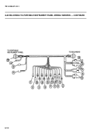
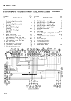
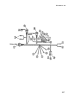
8-50 BULKHEAD-TO-DRIVER’S INSTRUMENT PANEL WIRING HARNESS — CONTINUED
a. Disassembly/Repair
WARNIN G
Ensure MASTER switch is OFF when working on hull electrical system to avoid
electrical shocks and bums.
1 Remove electrical tape only for sections to be disassembled.
2
Isolate and separate wiring harness branches.
3 Disassemble wiring harness branch (para 2-13) of wires to be replaced.
b. Assembly
WARNING
Ensure MASTER switch is OFF when working on hull electrical system to avoid
electrical shocks and burns.
1 Assemble wiring harness branch (para 2-13) of wires replaced.
2 Apply electrical tape as necessary for assembly.
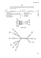
8-51 DRIVER’S INSTRUMENT PANEL WIRING HARNESS
This task covers:
a. Removal
b. Installation
Electrical tape — black (item 62, Appx D)
Batteries disconnected (para 8-28)
Portable instrument panel removed (para 8-17)
8-128
Back to Top

