TM-9-2350-311-34-2 - Page 402 of 552
TM 9-2350-311-34-2
9-2 NO-BACK BEARING - CONTINUED
b. Disassembly
1
2
3
4
5
6
7
8
9
10
11
12
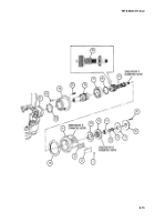
Remove traversing mechanism ring (14) ball bearing (15) and shouldered shaft (2) from mechanical hous-
ing (7).
Separate ball bearing (15) from shouldered shaft (2).
Remove woodruff key (16) from shouldered shaft (2).
Only if necessary for replacement, remove sleeve spacer (17) from mechanical housing (7).
Remove gasket (18) from bearing retainer (19). Discard gasket.
Straighten locking tabs on key washer (20).
Remove round nut (21) and key washer (20). Discard key washer.
Remove bearing retainer (19) from bevel gearshaft (22).
Note and record dimension “B” stamped on bevel gearshaft (22).
Remove retaining ring (23) and ball bearing (24) from bearing retainer (19). Discard retaining ring.
Measure and record thickness of ball bearing (24) for dimension "D" Also note and record dimension “C”
stamped on bearing retainer (19).
Separate upper drive bearing (25) lower drive bearing (26) lock ring (27) and lockbar (28) with six springs
(29). Discard springs.
c. Assembly
1
If removed, use an arbor press to install sleeve spacer (17) on shouldered shaft (2).
2
Assemble shouldered shaft (2) and ball bearing (15) with seal side out and install in mechanical housing (7).
3
Install traversing mechanism ring (14) in mechanical housing (7).
4
Install lower woodruff key (16) in shouldered shaft (2).
NOTE
Number of springs required in spring pack may vary depending on spring tension.
5
Apply lubricating oil to lockbar (28) and install six new springs (29) onto lower drive bearing (26).
9-8 Change 2
Back to Top


