TM-9-2520-234-35 - Page 57 of 323
PAR 30-31
DESCRIPTION AND OPERATION OF
CHAP 2, SEC IV
RIGHT- AND LEFT-OUTPUT DRIVE ASSEMBLIES
lubrication regulator valve. The pressure
maintained at this point is sufficient to
balance the compression of the spring
pushing the valve upward. This pressure
forces oil through the lubrication passages.
Oil flow in excess of lubrication require-
ments returns to the sump through an ex-
haust port at the right side of the valve
bore.
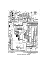
31. HYDRAULIC SYSTEM FUNCTION –
FIRST GEAR (fig. 7)
Note : Refer to par. 47 and fig. 23
for the torque path through the
power train.
a . Functions in first gear are the
same as those described for neutral in par.
30, above,
except that the low-rang e
clutch is engaged and the vehicle i s
moving.
b . When the manual selector valve is
moved to first gear position, a port is un-
covered which directs main pressure to
the low-range clutch Movement of the
manual selector valve lever puts a lug on
the lever in a position which will allow the
shift inhibitor plunger to extend an d
prevent shifting to neutral or reverse at
higher speeds.
c . When the vehicle is moving for-
ward with the brakes released, the brake
air valves (text continues on page 31)
Change 2 28.1/(28.2 blank)
Back to Top


