TM-9-2520-254-34 - Page 82 of 126
5-24. Cleaning
figure 5-74. Refer to paragraph 6-3 and table 6-3
Refer to paragraph 5-2 for cleaning recom-
for wear limits information.
mendations.
5-26. Assembly
5-25. Inspection and Repair
(fig. 5-74)
Refer to paragraph 5-3 for general inspection and
a.
If any anchor pins (18) are being replaced,
repair
recommendations. Repair and overhaul
press them into flat side of plate (16) until ends of
(rebuild) points of measurement for fits, clearances,
pins project 0.880 inch from flat side.
and wear limits are indicated by small letters in
b.
Install ten springs (19) in plate, and make
certain they are properly seated in holes.
Section VII. OVERHAUL (REBUILD) OF INTERMEDIATE-RANGE
CLUTCH PISTON HOUSING AND LOW- AND REVERSE-
RANGE CLUTCH PISTON HOUSING ASSEMBLIES
5-27. Description
(6) If either of two anchor pins (53) need
Refer to paragraphs 2-3 through 2-5 for description
replacing, pull pins from housing (52).
of the intermediate-range clutch piston housing and
(7) If any of six anchor pins (54) need
low-and
reverse-range
clutch
piston housing
replacing, press pins from housing (52).
assemblies.
5-28. Disassembly
(fig. 5-74)
NOTE
All related items not covered in
a
and
b
below or in separate rebuild sections, were
removed from the transmission as outlined
in paragraph 5-6, steps 40 through 45 (fig.
5-40 through
5-45). No
further
disassembly of those parts is required.
a. Intermediate-Range Clutch Piston Housing
Assembly
(fig. 5-74).
(1) Remove 12 springs (34) from housing
assembly (25) only if replacement is necessary.
(2) Tap housing assembly to loosen piston
assembly (22), and remove piston assembly.
(3) Remove outer seal ring (20) and expander
(21) from outer groove of piston.
WARNING
Do not dispose of Teflon seals by burning;
toxic gases are produced.
(4) Remove inner seal ring (24) and expander
(23) from inner groove of piston.
b.
Low- and Reverse-Range Clutch Piston
Housing Assemblies
(fig. 5-74).
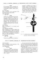
(1) Tap housing assembly (fig. 5-76) lightly to
loosen low-range clutch piston
assembly,
and
remove piston assembly.
(2) Remove reverse-range clutch piston (47) in
the same manner.
(3) Remove outer seal ring (49) and expander
(48) from low-range clutch piston.
(4) Remove outer seal ring (1, fig. 5-75) and
expander (2, fig. 5-75) from reverse-range clutch
piston (3, fig. 5-75).
(5) Remove low-range clutch piston hook-type
seal ring (50) and reverse-range clutch piston hook-
type seal ring (55) from housing (52).
LEGEND to, fig. 5-75 .
1 Clntch piston teflon seal ring
2 (Int[,h piston seal ring expander
3 Reverse-range clutch piston
4 I{everse-range
clutch apply plate
.3
Reverse-ranKe clotch rotating plate
6 Re\ersc-range ring gear assembly
7 Re\erse-range clutch stationery plate
8 Reverse-range clotch rotating plate
‘) I{ekerse-range clutch stationary plate
1() I{everse-range
clutch rotating plate
I
1
Reverse-range clutch stationary plate
12 l{evrrse-range clntch rotating plate
I
3 (;lntch piston rrtorn spring ( 12 )
14 I{everse-range
clotch back plate
1.3 Ancll(,r I)in retainer roll-type pin ( 2 )
1
() ‘1’llrust washer
17 1{ m erse-range son gear
1
X SIIn gear snap ring
] () S,III gear sl]aft thrust washer
20 olltl)llt sl]aft snap ring
21 l{e\erse-range planetary carrier assembly
22 Spindle (())
?:i l’init)]l thnlst ],asher (())
24 I’initjtl thrust washer (6)
‘l; l~i],if,]] [(, )
20 l)init)t] roller ( 120)
27 l’ini(,tl tllrt]st nasher (())
2}{ I’ini,,n tltnist \\asller (61
2° ‘I{t,ar I)itf)t ct)llect{)r ring
J() C,,llett{)r ring rivet ( 3 }
:! I (:f,llett{,r rinu \vasller ( 3 )
:]j Ii{, er,e-rallg~ planetary carrier
:\:] l{ear pit{)t tllbe
:!4 I{ear oil pun]l) Ix)lt (3 I
:}.; I,t,(kti asl}er (,3 I
:)() I{t,ar oil },IImp assembl]
:17 1’(11111)
1)()(1}
:)}; l)ri~etl gear
:!() l)ri\ e gear
10 l’IIml~ {x~~(,r
11
(;asket
5-32
Back to Top


