TM-9-2815-200-35
ENGINE, WITH CONTAINER:TURBOSUPERCHARGED, DIESEL ,FUEL INJECTION ,90-DEGREE “V” TYPE, AIR - COOLED ,12 - CYLINDER , ASSEMBLY ;MODELS AVDS-1790-2M (2815-856-4996), AVDS-1790-2A AND AVDS-1790-2AM (2815-856-9005)
TECHNICAL MANUAL; DIRECT SUPPORT, GENERAL SUPPORT AND DEPOT MAINTENANCE MANUAL INCLUDING REPAIR PARTS AND SPECIAL TOOLS LISTS
TM-9-2815-200-35 - Page 44 of 779
f.
The engine crankcase is vented by an en-
closed crankcase breather system which is vented
through the crankcase breather tube (fig. 1-7) at
the left turbosupercharger exhaust pipe.
g. The engine primary and secondary fuel
filters (fig. 1-3) have individual drain lines, with
drain cocks, which provide a means of draining
the filters to remove water which may be ac-
cumulated and to purge the fuel system. Late
production AVDS-1790-2A engines have a
filter / water separator type secondary filter and
drain lines to remove entrained moisture from
the fuel (fig. 1-6).
1-9. Accessories
Refer to paragraph 1-2 for information on
engine accessories.
1-10. The crankcase
(fig. l-l) is a one-piece
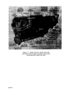
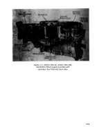
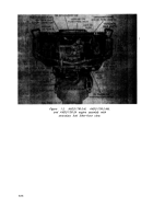
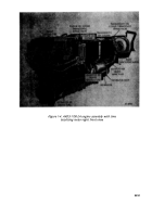
Figure 1-8. Legend
A - Intake valve rocker arm assembly
B - Exhaust valve rocker arm assembly
C - Left camshaft assembly
D - Camshaft driven gear
E - Camshaft drive gearshaft
F - Camshaft drive shaft
G - Camshaft drive bevel gearshaft
H - Accessory drive gearshaft assembly
J - Fuel injector pump advance assembly
K - Right camshaft assembly
L - Transmission accessory drive gearshaft
M
- Accessory drive gear
N - Flywheel
P - Generator drive gearshaft
Q - Generator idler gear
R - Oil pump driven gear
S - Piston cooling oil pump driven impeller
T - Pressure oil pump driven impeller
U - Scavenge oil pump driven impeller
V - Oil pump driven shaft
W - Scavenge oil pump drive impeller
X - Scavenge oil pump driven impeller shaft
aluminum casting with forged aluminum main
bearing caps. The bearing caps function as an
integral part of the crankcase. Each cap is
secured on studs with four slotted nuts. Two
through bolts clamp the main bearing cap in the
tunnel slot of the crankcase. With this type of
crankcase and bearing cap construction, uniform
load distribution in the bearing area is obtained
making possible uniform distribution of com-
bustion forces over the entire crankcase.
1-11. Main Bearings
The seven replaceable main bearings are the
steel-backed, split type, having copper-lead alloy
bearing surfaces. The center main bearing is
double-flanged with bearing material to control
crankshaft end play and thrust.
Y - Pressure oil pump drive impeller
Z - Piston cooling oil pump drive impeller
AA - Oil pump drive gear
BB - Starter idler gear
CC - Starter driven gearshaft
DD - Starter drive gear
EE - Front fan drive shaft
FF - Fan drive bevel gearshaft
GG - Rear fan drive shaft
HH - Fan driven gearshaft
JJ - Fuel injector pump drive gear shaft
KK
- Fuel injector pump driven shaft gear
LL - Fan drive clutch assembly
MM - Cooling fan adapter
NN - Rear cooling fan assembly
PP - Fan drive bevel gearshaft
QQ - Crankshaft assembly
RR - Fuel pump drive coupling
SS - Fuel pump drive adapter
TT - Crankshaft torsional vibration damper
UU - Connecting rod assembly
VV - Piston
WW - Front cooling fan assembly
XX
- Exhaust valve
YY - Intake valve
1-4
Back to Top

