TM-9-2815-202-34 - Page 230 of 670
TM9-2815-202-34
4-32. OIL PUMP REPLACEMENT
(Cent)
NOTE
Install spring washer with crown side toward bolt.
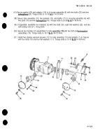
(10) Position spurgear (28)onto drive shaft (34)and secure withspring washer (27)and bolt
(26). Tighten bolt to install spur gear. Torque bolt to 60-65 Ib-ft (81-85 N-m). Remove oil
●
pump housing (32) from soft-jawed vise and rag from gears (38 and 39).
(11 ) Install
(12) Install
(13) Install
(14) Install
two remaining woodruff keys (40) onto drive shaft (34).
spacer plate (37) on shafts (34 and 36).
scavenger side helical gear (33) onto drive shaft (34).
scavenger side oil pump gear (35) onto driven shaft (36) .
NOTE
The scavenger side oil pump gear and helical gear must be in the same relative
position as the oil pump gear and helical gear on the housing side.
(15) Position shafts (34 and 36) into scavenger pump housing (31 ) and join with oil pump
housing (32). Secure housings with four bolts (30). Torque bolts to 30-35 Ib-ft (41-47 N-m).
NOTE
●
Oil pump gears must turn freely. Any bind in pump gears must be eliminated before oil
pump is installed on engine.
(16) Install gasket (47) and access cover (46) to oil pump housing (32) and secure with screw
(43), bolt (44), and Iockwasher (45). Torque bolt to 23-26 Ib-ft (31-35 N-m).
4-128
Back to Top


