TM-9-2815-205-24 - Page 31 of 856
TABLE OF CONTENTS - Continued
Page No.
WP Sequence No.
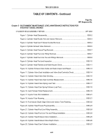
Chapter 5 - SUSTAINMENT MAINTENANCE LEVEL MAINTENANCE INSTRUCTIONS FOR
6V53/6V53T DIESEL ENGINES
CYLINDER HEAD ASSEMBLY REPAIR.
..........................................................................................
WP 0083
Figure 1. Cylinder Head Disassembly.
........................................................................................
0083-2
Figure 2. Cylinder Head Rocker Arm and Injector Removal.
.......................................................
0083-3
Figure 3. Cylinder Head Cam Follower Guides Removal.
...........................................................
0083-4
Figure 4. Cylinder Exhaust Valve Removal.
................................................................................
0083-5
Figure 5. Cylinder Head Freeze Plug Removal.
..........................................................................
0083-7
Figure 6. Cylinder Head Fuel Line Fitting Removal.
....................................................................
0083-7
Figure 7. Cylinder Head Fuel Line Tee and Fittings Removal.
....................................................
0083-8
Figure 8. Cylinder Head Test and Inspection.
...........................................................................
0083-10
Figure 9. Cylinder Head Flatness and Water Nozzle Check.
....................................................
0083-11
Figure 10. Cylinder Exhaust Valve Guide and Seats Inspect and Repair.
................................
0083-13
Figure 11. Cylinder Valve Seat Installation and Valve Seal Centricity Check.
..........................
0083-14
Figure 12. Cylinder Head Valve Seat Grinding.
.........................................................................
0083-15
Figure 13. Cylinder Head Valve Seat Centricity Measurement.
................................................
0083-16
Figure 14. Cylinder Head Valve Spring Load Test.
...................................................................
0083-17
Figure 15. Cylinder Head Cam Spring Follower Load Test.
......................................................
0083-18
Figure 16. Cam Follower Roller Replacement.
..........................................................................
0083-19
Figure 17. Injector Tube Pilot Installation.
.................................................................................
0083-21
Figure 18. Injector Tube Reaming.
............................................................................................
0083-21
Figure 19. Fuel Injector Depth Gage Check and Injector Tube Reaming.
.................................
0083-22
Figure 20. Cylinder Head Freeze Plug Assembly.
.....................................................................
0083-23
Figure 21. Cylinder Head Fuel Line Fitting Assembly.
...............................................................
0083-24
Figure 22. Cylinder Head Fuel Line Tee and Fittings Installation.
.............................................
0083-24
Figure 23. Cylinder Head Exhaust Valve Installation.
................................................................
0083-25
Figure 24. Cylinder Head Exhaust Valve Depth Check.
............................................................
0083-26
Figure 25. Cylinder Head Cam Follower Installation.
................................................................
0083-27
TM 9-2815-205-24
xvii
Back to Top


