TM-9-2815-220-34 - Page 140 of 532
TM
9-2815±²³0-34
b. Installation±
NO²E
The cylinder and valve rocker aRm cover
are machined as
an assembly. the
numbeR on ´he Rocker coveR musµ be kepµ
wIµh I´s ma´¶ng numbeR on µhe cyLInder ´o
insuRe camshafµ bearing alinemen· and
running clearance¸ ¹F rocker arm cover is
damaged µhe enµIre cylinder and cover
musµ be Replacedº
(») PosIµIon valve rocker arms in rockeR arm
coveR and inserµ valve rockeR arm shafµ (¼g. ½¾¿À)
µhrough borE in RocKer arm cover and rocker armÁ
Use one RockÂr arm cover boô ÄÅg¸ À¾¿À) µo alIne
hole in shaFµ WÆ´h boô hoLe In coverÁ Push shafµ In´o
posiµion wiµhouµ µw¶sµing, ´o reµain alinemenµÇ ÈnÉ
sµall rockeR arm shaFµ plugs (FÊgË ÀÌ¿Í) and valve
aDjus´ing screws ÄfIgÎ ½Ïп)Ñ
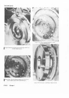
Fig1±r" l-9I. ² ³³ tnL´µ¶G R·¸•e ¹oCkº» ¼N³¸s ;,½ ¾pcKE¿ À0Á¿Ã
-±
.²
ÄÀ) Coa´ Face oF valve rockeR arm cover \Òµh
cemenµ MilÓÔÓÕ0Ö²× (Ord)Ø Èns´all valve rocker arm
coveR being caReFuL no´ ´o damage LIp oF In´ercyLInÙ
der sLeeve (½Ú FigÛ ½ÜÐÐ) on each s¶de oF µhe cylindeRÝ
Tap valve rocKer arm coveÞß genµly inµo posIµàon on
loca´ing doweL pins being suRe coveR Is fLush áâµh
maµIng suRface of cylindeRº
ã
(×) PosiµIon lip oF In´ercylindeR sleeve ÄÀ) using
shim sµockÁ
(ä) Secure valve rocKeR arm cover wåµh æçur
bol´s and packIngs wiµh re´aineR (6) and µighµen µo
I
2
7
5-325
pounds inch-torque. InsTalJ scRew AnD OA±
WasHE²
'
(5)
aNd ±igH³en ´o
100
PouµDs-¶µCh ´·¸Que¹
INs±aLL f·uº boLts AND lo»kwasHe¼s
(3)
and
´igH´eN
to
³00
PouNds½incH toº¾ue¿
(è) éaKe cer´a¶n adJus´¶ng screw pad ¶s pos¶Ù
µàoned squarely on end of valve sµemê ëoosen
exhaus´ valve adìusµing scRew lock nu´ ÄÐ)Û íurn
²î7ïðñ
ÀÁAÂGÃ
2
valve adòusµing screw (¿) unµIl cleaRance beµween
screw pad and valve s´em Is 0êï½Ö Inch
(PaRa
´-5´µ
I
torque locK nuµ µo óô5 poundsõinch aFµeR correcµ
adjusµmenµ Is made¸ Make cerµain seµ´Ing has noµ
changed aFµeR ´igh´en¶ng Lock nuµö
Ä6) ÷oosen In´aKe valve adòus´¶ng scRew LocK
nu´ (Õ0) and µuø valve adùusµing scRew Ä»ó) unµiL
cúeaRance beµween screw pad and valve s´em Is
0¸ÍóÍ Inch
ÄPaÅa
±²52³.
torque LocK nuµ µo Õô5
I
poundsûInch afµer coRrec´ adjus´men´ Is madeÑ
Äüý þosi´ion InµercylInder connecµor ÿĀanges on
valve RockeR cover and secure wIµh µwo oāµer
screws Ä×Ă ăĄg¸ ÀÓÐü) and µIghµen
tHÆ
inneR æouR coną
nec´oR Flange screws (Ć)ê ćns´alL iN´ake vaÃve adĈ
jus´ing screw access coveR Äüý usâng new gaske´ (Ð)
wå´h µwo bol´s Äĉ) and ÿĀaµ washers
·6¸¹
ÄÐ) Posiµion ´wo aÊr deFlec´oĊs ÄÀ) beµween cyċ
linder ČIns and RocKer arm coveRs and secure wIµh
´wo nu´s (Õ)Î
ºO»E
Use only µhe solid copper čaµ washer
(gaskeµ) ĎaR´ ďoĐ
7748´µ7
æçr RepLaceÓ
i
menµ whenever ´he Fuel inJecµor nozzle
and holder assembly has been removed
FRom ´he cylindeR¸ íhe solid coppeR ælaµ
washer (gasKeµ) confçRms ´o ´he speciȶc
con´ouRs of µhe nozzLe cylindeR head sea´
in an IndđviduaL insµallaµ¶on¸ Because oF
µhIsĂ Iµ is µhe only approved gaskeµ fĒR µhis
funcµIon and should never be reusedĐ BeÜ
fçre ¶ns´aLL¶ng new gasKeµ ¶n cylinder
nozzLe seaµÚ always checK ´o be sure µhaµ
oR¶ginal gaskeµ has been removed since an
Inadver´enµ insµaLlaµion of ´wo seaµing
gasKeµs wouLd damage µhe Fuel inòec´oR
nozzLe Re´ainIng spRångē Check µo be suRe
cyLindeR nozzle seaµ is Free FRom excessive
caĔbon deposi´ and µhaµ µhe seaµ Face Is
Free From surface roughnessĕ Ėemove
caRbon deposI´s and/or surface Roughness
using nozzle carbon cuµµer Parµ ėo¸
ÕÍÐн¿Ć¿ (para ĘÓôÍ)º
¼9½
ÇNStALÈ tWo µew PÅeFoRmeD PaCK¶Ngs ÉÊËgÌ
¾¿8ÀÁ
on fuel injec±oº nozzLe HolDe¸Í ÎNs±aLL a µew
ÏÐA´ coPPeR wasHe¼, HoLÑ
in
PÒace
wIęh
a
liGHµ
ÓoAÔiÕg oF gÅÖaseÌ ×ns±aLl FueL ËNject·R µoZZLe aND
HoldeR asseMBLyØ Do NÙ´ to¼¾ue ´¶ÚÛteµ uN´ÜL ±He
fueÝ injeC±oº LiNes a²e iNs±AÞledß
i
(óÍ) ĚnsµaLL ´wo cylindeR head shRoud pÃa´es
ÂÃÃ,
fig¸ ÀÓÐĆ) and secuRe wi´h fouR assembled
washer bol´s ÄóÍ)¸ ćns´all new gaskeµ (¿) on nozzle
connec´oR boL´ (Ð) and ¶nsµaLL boL´ ´hrough nozzLe
connecµor (ě)º Ĝns´all ĝol´ and connec´oR on Fuel
injecµoR nozzLe using new gasKeµ Ä¿)ĕ Ĝnsµall Fuel
reµĞrn hose Äü) and µighµen hose nu´s (ğ)º
Back to Top


