TM-9-2815-224-34-P - Page 179 of 554
TM 9-2815-224-34&P
CHAPTER 7
VALVE MECHANISM MAINTENANCE
Contents
General . . . . . . . . . . . . . . . . . . . . . . . . . . . . . . . . . . . . . . . . . . . . . . . . . . . . . . . . . . . . . . . . . . . . .
Valve Bridge Guide Removal/Installation. . . . . . . . . . . . . . . . . . . . . . . . . . . . . . . . . . . . . . . . . .
Valve Guide Removal/Installation. . . . . . . . . . . . . . . . . . . . . . . . . . . . . . . . . . . . . . . . . . . . . . . .
Exhaust Valve Removal/Repair/Installation. . . . . . . . . . . . . . . . . . . . . . . . . . . . . . . . . . . . . . . .
Rocker Arm Removal/Repair/Installation . . . . . . . . . . . . . . . . . . . . . . . . . . . . . . . . . . . . . . . . .
Cam Follower/Push Rod Removal/Installation . . . . . . . . . . . . . . . . . . . . . . . . . . . . . . . . . . . . .
Cam Follower Repair . . . . . . . . . . . . . . . . . . . . . . . . . . . . . . . . . . . . . . . . . . . . . . . . . . . . . . . . . .
Exhaust Valve Bridge Removal/Installation. . . . . . . . . . . . . . . . . . . . . . . . . . . . . . . . . . . . . . . .
Camshaft Removal/Repair/Installation. . . . . . . . . . . . . . . . . . . . . . . . . . . . . . . . . . . . . . . . . . . .
Camshaft End Bearing Bushing Removal/Installation . . . . . . . . . . . . . . . . . . . . . . . . . . . . . . .
Idler Gear Removal/Repair/Installation . . . . . . . . . . . . . . . . . . . . . . . . . . . . . . . . . . . . . . . . . . .
Front Balance Cover and Vibration Damper Removal/Installation . . . . . . . . . . . . . . . . . . . . .
Section I.
INTRODUCTION
Para
7-1
7-2
7-3
7-4
745
7-6
7-7
7-8
7-9
7-10
7-11
7-12
Page
7-1
7-1
7-3
7-5
7-8
7-11
7-15
7-16
7-20
7-34
7-36
7-43
7-1. GENERAL. This chapter covers removal, installation, and repair of the valve mechanism. The
subassemblies and parts which must be removed before these components can be removed will be
referenced to other paragraphs of this manual, TM 9-2320-279-10, TM 9-2320-279-20, or TM 9-2320-279-34.
Section II.
VALVE MECHANISMS
Valve Mechanism Maintenance Instructions
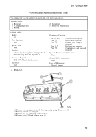
7-2. VALVE BRIDGE GUIDE REMOVAL/INSTALLATION.
This task covers:
a. Removal
c. Follow-on Maintenance
b. Installation
INITIAL SETUP
Models
Equipment Condition
All
TM or Para
Condition Description
Test Equipment
Para 11-2
Engine brake retarder
None
removed.
Special Tools
Para 7-5
Rocker arms removed.
Para 7-8
Exhaust valve bridges
Installer, valve bridge guide J7482
removed.
Supplies
Para 12-2
Fuel injectors removed.
None
Para 7-4
Exhaust valves removed.
Personnel Requi red
Special Environmental Conditions
MOS 63W Wheel vehicle repairer
None
References
General Safety Instructions
None
None
Level of Maintenance
General Support
7-1
Back to Top


