TM-9-2920-258-30-P - Page 60 of 76
TM 9-2920-258-30&P
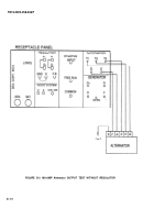
10 Using a multimeter, place the red lead on terminal “ac” and ground the black lead. Check for 12-
16 volts AC.
11 If the Alternator meets the above requirements, it is serviceable.
e
Test Stand Shutdown
1 Turn the field current (0-30 amps) counterclockwise.
2 Turn the battery select switch to the OFF position.
3 Turn the master load switch to the OFF position.
4 Turn the speed control clockwise and reduce speed to 1000 rpm.
5 Depress the STOP button.
6 Return ail switches to the base setting.
D-3
Testing Procedure With Regulator
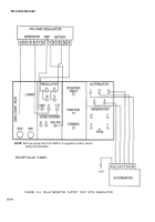
Refer to TM 9-4910-663-12 for test stand general preparation and operation procedures. Use the following
information for testing procedures specific to the 180 ampere Alternator (ref Figure D-4).
a
Preparation
1 Connect the test cable to the Alternator.
2 Mount the Alternator on the test stand.
3 Set the controls and switches of the test stand to the base setting. The base setting is as follows:
A
DC bad ammeter range switch at X 10.
B
DC field ammeter range switch at X 6.
C
Millivottmeter range switch at X 10.
D
DC voltmeter range switch at X 5.
E
DC voltmeter select switch in the RECT/GEN position. (NOTE: Select switch position for test
stand model 7458-4 set to EXT.)
F
AC ammeter range switch at X 5.
G
AC ammeter select switch in the T1 position.
H
AC voltmeter range switch at X 2.
I
AC voltmeter select switch in the T1-T2 position.
J
External field exciter switch (AC system) in the OFF position.
K
Generator field in the INT GND position.
L
Polarity reversing switch in the NEG GND position.
D-1 2
Back to Top


