DMWR-9-2815-220 - Page 165 of 1422
·.
±
²³
-
±
²
.
·-±²³
³´µ¶·¸
_
´.±
¹
µ
¹
DMWR 9-2815±220
5-13.
(Cont)
(b±
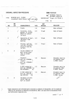
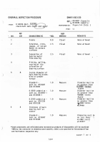
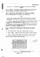
DimensIonal changes²
To detec³ diMNsioNal chaNGes caused by weldiNG
repa´r, precµsely ¶asure craNkcase a³ severaL Key posI³Ions dependING upoN ³he
loca³io· of ³he repaIr¸
For repair ³o side walls, measUre ³he posI³IoNs outl¹ned
beLow²
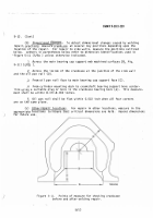
ºe³³ers in parentheses be»ow refer ³o d¼¶nsioN iden³I½Ica³Ions used iN
¾fiGUre ¿À1Á (Â/Â0 ± UNÃess otheRise iNdica³ed.
²
Across ³he Äain beariNG cap sÅppor³ We ÆchIned sur½aces JÇiGÈ
Â-1ɱ (
Ê
/
SO
±
•
2
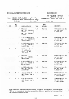
Across ³he Inside of ³He craNKcase at ³he jÅNc³ioN of the side ËaÌL
aNd the oÍl paN rail ÎD±Ï
3
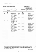
FroÐ oil pan raIl ½ace to main bearinG cap support face (ѱ²
4
ÒroÐ cylinder moÅNtiNG decK ³o cranÓsha½³ beariNG sUpport bore cen³erÔ
LiNe ÅsinG a sUI³able plUG or bore iN the cranKcase bearinG bore (Õ±²
Th¼s measUreÔ
meNt shall be within
8.37±-8²369
Inches²
Â
ÖiL pan raIl shaLl be ½la³ withIn ×.×Á× INch wheN all Øour corNers
are oN thE same pLaNeÏ
(c±
Öther rePaIr locatIonsÙ
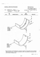
Úor repair in o³her »ocationsÛ ÜeasurÝ in the
appropria³e Þoca³ßons to ànsUre táat crI³Ical dimensions are heâd.
ãecorä dimensions
å
½ær fųure Use²
)
³´eµ
c
t
·¸¹
D º»¼½¾
TA0¿ÀÁ¿
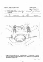
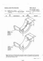
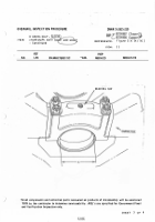
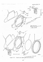
çiGÅre èéÉɸ
êoInts o½ ¶asUre ½or checëInG craNìcase
be½ore and after weldinG repaIrÏ
Â/íî
Back to Top

