DMWR-9-2815-220 - Page 323 of 1422
)
DMWR 9·2815±220
5-37.
Repair and Assembly±
a²
GeNeral RePaIr³
Refe´ to pa´agraph 5µ5 (5/5
) Fo´ gene´aL ´epaI
Instructions·
b.
CYlInder ¸nterIor.
(1±
Valve ¹UiDe ´e
º
lacemeNt±
Replace any »ra»ked, gaLlEd¼ e´oDed½ o
s»uFFed ¾NtaKe aN¿ exHaust vaÀve guides¼ o´ gUIDes that Do Áot coNFoÂM to ÃImIts
UsiNg tÄe folLowINg procedUre.
NOTE
ÅNtaÆe aNd exhaust vaÃve guides are ´emoved f´om tÄe cylinder In the
same manNer²
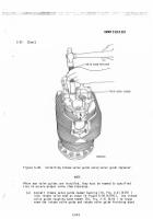
The ¾NtaÆe valve guIde mecÇanIcal PUlle´ (5¼ fIg³ 2-4)
(
2/12 ) Is UseD fo´ INtaÆe valve gUiDe removaL and tÄe Exhaust valve
gUIde mecÄaNIcaà puÃÃeÈ É4½ Fig. 2-4) É2/Ê2 ) Is useË for exÄaust valve
guIDe removaÃ.
·
(aÌ
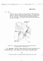
¸Nsert sc¶ew of mecÄanicaL puller through the vaÃve gUIde aÁd puÃler
and iNstalà ÁUt on tÄe eÁd oF pulÃe´ sÍ´ew (fIg. 5-36Ì (5/Î9Ï ).
дeheat enti´e assembly in oveN to 350 deg´ees Ñ Maximum BefoÒe
removing valve gÓIde.
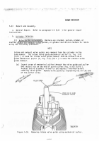
Remove vaLve guIde by tighteNIng NUt oÔ the enD
oF the PUlle´ sc´ew.
.
-1d/
±
²
,.
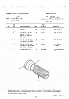
INTAKE VALVE GUIDE
MeCHa/1 CAL Pull±R
ÑIgu´e 5Õ36Ö
RemovIng intaÆe vaÃve guide usiNg mechaÁicaà pulLe´.
I,±
0²
Back to Top

