MWO-9-1290-365-20-1 - Page 7 of 12
7
MWO 9-1290-365-20-1
(a)
Unscrew and remove 16 screws (6), 16 lock washers (7), and 16 flat washers (8) from four
resilient mounts (5).
(b) Remove and set aside for disposition per paragraph 8d, four resilient mounts (5) from
bracket (4).
e.
PROCEDURES FOR ASSEMBLY:
(1)
Resilient mounts to antenna-mounting bracket.
Install the
following parts in accordance with the
following steps and figure 3:
(a)
Install four new (blue) resilient mounts (5) in the place of the four removed during disassembly.
NOTE:
Blue resilient mounts must be installed with the hex nut visible from the backside of bracket.
(b)
Insert and tighten 16 new screws (6), 16 new lock washers (7) and 16 new flat washers (8).
(c)
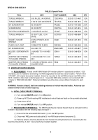
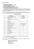
Using a cross-tip torque wrench (table 5), tighten the mounting screws to between 20 and
25 in-lb (1.66-2.08 ft-lb).
NOTE:
One antenna-mounting bracket off of one M109A6 howitzer will be used for all system check-
outs at the time of hand-off or fielding of the upgraded M93 transceiver.
When the upgraded
transceiver is placed on a different howitzer, and an old transceiver is removed, that is when each
antenna-mounting bracket will have the new resilient mounts installed.
(2)
Transceiver to antenna-mounting bracket.
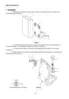
Install the following parts in accordance with the following
steps and figure 2:
(a)
Correctly position transceiver (4) on bracket (3).
(b)
Install four new screws (1) and four new lock washers (2).
(c)
Using a hex head torque wrench (table 5), tighten each mounting bolt to between 60 and 70 in-lb
(5.00-5.83 ft-lb).
WARNING:
Remain at least 2 feet from radiating antennas of vehicle-mounted radios.
Antennas can
radiate harmful levels of radio frequency.
f. INSTALLATION:
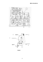
Install the transceiver and mounting bracket to the howitzer
in accordance with the
following steps and
figure 1.
(1)
Ensure that the vehicle
MASTER
switch (1) is in the
OFF
position.
(2)
Position antenna-mounting bracket (3) on howitzer bracket (4).
(3)
Secure with hex head mounting bolt (1), lock washer (2) and flat washer (3) as noted in figure 3.
(4)
Install mounting bracket with attached transceiver to the howitzer's bracket and torque main bolt to
between 450 and 500 in-lb (37.5-41.67 ft-lb).
(5)
Connect W92 power and data cable (Fig. 1, Item 5) to M93 (upgraded) transceiver (Fig. 1, item 2).
(6) Turn vehicle
MASTER
switch (1) to
ON
position.
(7)
Power up AFCS with M93 (upgraded) transceiver installed; note any data and/or faults on the data
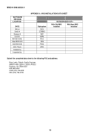
sheet provided at appendix A.
NOTE:
If there is a BIT failure with an upgraded M93 receiver/transmitter, repeat installation using the
same serial numbered M93 on a different M109A6 howitzer that has already had the MWO applied.
If the
same M93 (upgrade) fails on a second M109A6, return to contractor for analysis/repair.
(8) Power down the AFCS and return the vehicle
MASTER
switch to the
OFF
position.
(9) Remove the upgraded M93 transceiver IAW paragraph 10c through 10d(1)(b).
This transceiver is
now ready to install on any M109A6 howitzer equipped with new resilient mounts.
(10) Using the same M109A6 and antenna-mounting bracket, repeat the steps in paragraphs 10e(2)
through 10f(9) for each M93 (upgraded) receiver-transmitter.
Back to Top

