MWO-9-2300-378-34-2 - Page 65 of 92
Section VI.
(1) Assemble
MWO 9-2300-378-34-2
Hull Wiring Instructions for M48A5 and M60A1 AVLB
smoke generator switch bracket (refer to section II).
NOTE
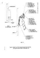
Figures 48, 49 and 50 correspond to the M60A1 AVLB.
Figures 51, 52 and 53 correspond to the M48A5 AVLB.
Figure 54 is common to both.
(2) Remove and discard two screws MS90726-6 and two lockwashers MS35338-44 from
the left side of the master control panel.
Then install the previously assembled switch bracket
assembly to the master control panel using two screws MS90726-9 and two lock washers
MS35333-40 (refer to figure 54).
(3) Drill one hole in support 10934246 as shown in figure 54.
(4) Connect the kit wiring harness switch receptacle to the switch connector and
secure the harness with one clamp MS21333-100, screw MS90726-7, lockwasher MS35333-40,
and nut MS51968-2 to the support 10934246 (refer to figure 54).
(5) Remove and retain one screw MS90725-5 and flat washer MS27183-10 from each
of the wiring harness securing straps 10905840 as shown in figures 49 and 52.
(a) Remove lockwasher MS35333-33 from each wiring harness securing straps on
the M60A1 AVLB and replace with lockwasher MS35335-33.
(b) Remove and retain to be re-used, each lockwasher MS35338-44 on all
securing straps of the wiring harness, on the M48A5 AVLB.
(6) Route the kit harness 12270526 along the existing harness to the air cleaner
blower motor relay.
Disconnect the relay receptacle and connect the kit harness spliced jumper
into the relay circuit (refer to figures 48 and 51).
(7) Secure the receptacle and excess cable with two straps MS3367-6-9 as shown in
figures 49 and 52.
(8) Route the single lead of the kit wiring harness along the existing harness up to the
starter harness receptacle (refer to figures 48, 49, 51 and 52).
(9) Remove the electrical disconnect access plate (figure 28, view D) and disconnect
the starter harness receptacle from the bulkhead.
Remove the existing filler rod and contact
from pin location “A’
f
and insert lead assembly 12290435 contact into this location. Reconnect
the receptacle connector to the bulkhead and install the access plate (refer to figures 48, 51
and 28, view D).
(10) Secure the total wiring harness with the previously removed straps 10905840
(refer to figures 49 and 52).
(11) Remove and discard the existing identification band of the starter cable assembly
at the positive bus and apply identification band M43436/1-3 with the new part number
12290741 for M48A5 AVLB’S or No. 12290743 for M60A1 AVLB’S (refer to figures 48 and 51).
NOTE
Check harness routing and connect ions to insure a neat
and secure installation.
63
Back to Top


