MWO-9-2320-272-20-8 - Page 5 of 18
MWO 9-2320-272-20-8
b.
Accelerator Linkage Modification Kit Installation.
(1)
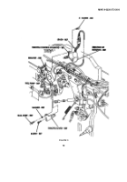
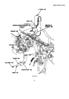
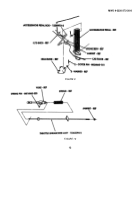
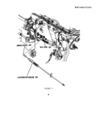
Transfer mark from existing throttle lever to 12363633-1 throttle extension lever as shown in figures 5
and 7.
(2)
Install MS35335-61 washer and ball joint on throttle lever extension (12363633-1) with B18244B06 nut
as shown in figure 7.
(3)
Install throttle lever extension (12363633-1) on fuel pump with existing screw and B18234B06016N
screw as shown in figure 7.
NOTE
Align shoulder pin to mark on throttle extension lever.
(4)
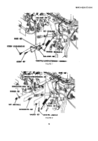
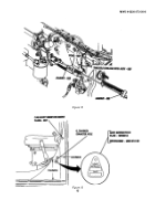
Install shoulder pin on throttle lever extension (12363633-1) with washer and MS51943-2 nut as
shown in figure 8.
(5)
Install modulator cable on throttle lever extension (12363633-1) and shoulder pin with washer and
AN415-8 lock pin as shown in figure 8.
(6)
Install spring on throttle lever extension (12363633-1) as shown in figure 8.
(7)
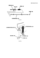
Install 12255972-2 accelerator pedal rod on bellcrank and accelerator pedal with two existing washers
and MS24665-151 cotter pins as shown in figure 9.
(8)
Loosen jamnut and adjust stopscrew 0.75 in.
(19.1 mm) from cab floor as shown in figure 9.
Tighten
jamnut.
(9)
Install spring and yoke on 12363294-2 throttle linkage rod assembly with MS 16562-223 spring pin as
shown in figure 10.
NOTE
Before performing next step, refer to Section ’A", step ’7".
(10)
Install jamnut on throttle linkage rod assembly (12363294-2) to previously noted position as shown in
figure 10.
Finger tighten jamnut.
WARNING
Bend end of throttle control cable away from bellcrank to prevent accelerator pedal from binding.
Failure to do so may result in injury to personnel or damage to equipment.
(11)
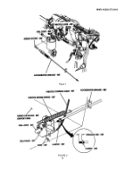
Bend end of throttle control cable away from bellcrank as shown in figure 2.
(12)
Install accelerator linkage into ball joint on bellcrank as shown in figure 2.
(13)
Connect throttle return spring on accelerator linkage as shown in figure 2.
(14)
Depress spring socket and install accelerator linkage on ball joint as shown in figure 11.
5
Back to Top

