MWO-9-2320-280-20-7 - Page 6 of 25
9.
SPECIAL TOOLS; TOOL KITS; JIGS; TEST, MEASUREMENT, AND DIAGNOSTIC EQUIPMENT (TMDE); AND
FIXTURES REQUIRED.
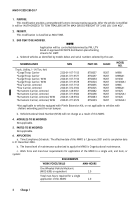
a. Hand tools necessary to apply MWO are contained in following tool kit:
NOMENCLATURE
NSN
CAGEC
SUPPLY CATALOG
Tool Kit, General Mechanic’s
50980
SC 5180-95-N26
b. Tools necessary to apply MWO are contained in following shop set:
NOMENCLATURE
NSN
CAGEC
SUPPLY CATALOG
Shop Equipment, Automotive
19204
SC 4910-95-A74
Maintenance and Repair:
Organizational Maintenance,
Common No. 1
10. MODIFICATION PROCEDURE.
a. Vehicle Preparation.
(1) Park vehicle and apply parking brake lever. (Refer to TM 9-2320-280-10.)
(2) Remove pioneer tool stowage tray mounting bracket. (Refer to TM 9-2320-280-20.)
(3) Remove tools from pioneer tool stowage tray. (Refer to TM 9-2320-280-10.)
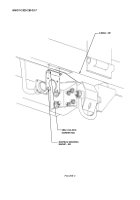
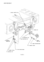
(4) Remove cotter pin, slotted nut, washer, and towing pintle from rear frame channel as shown in
figure 1. Discard cotter pin.
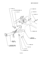
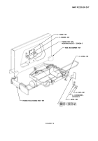
(5) Remove four locknuts, screws, cover, and receptacle from receptacle mounting bracket as shown
in figure 2. Discard locknuts.
NOTE
• If receptacle mounting bracket is held on D-beam with
rivets, perform step 6. If not, perform step 7.
• Sealing compound may have been used to adhere
receptacle mounting to D-beam and may require some
prying to remove from D-beam after hardware is
removed.
(6) Remove two rivets and receptacle mounting bracket from D-beam as shown in figure 2.
(7) Remove two locknuts, screws, washers, and receptacle mounting bracket from D-beam as shown
in figure 2. Discard locknuts.
NOTE
If receptacle mounting bracket was riveted to D-beam,
enlarge both holes in receptacle mounting bracket and
existing hole in D-beam on left side to 0.344-inch
diameter.
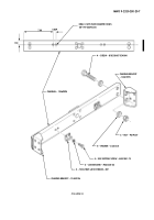
(8) Align right side hole in existing receptacle mounting bracket with left side hole on D-beam and
using receptacle mounting bracket as a template, locate, mark, and drill 0.344-inch diameter hole
in receptacle mounting bracket and D-beam as shown in figure 3. Remove receptacle mounting
bracket.
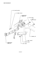
(9) Remove eight nuts, sixteen washers, and eight screws from two rear frame channel mounting
brackets and left and right frame rails as shown in figure 4.
MWO 9-2320-280-20-7
4
Back to Top

