MWO-9-2320-280-20-7 - Page 7 of 25
.
WARNING
.
Rear frame channel must be supported before removing
inner brace support brackets. Failure to support rear
frame channel may result in injury to personnel.
NOTE
It may be necessary to loosen mounting hardware on two
rear frame channel mounting brackets in order to
remove rear frame channel.
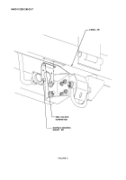
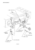
(10) Remove two nuts, four washers, two screws, inner brace support brackets, and rear frame
channel from left and right frame rails as shown in figure 4.
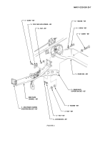
(11) Remove four nuts, lockwashers, screws, and two tool tray latch strikers from rear frame channel
as shown in figure 4. Discard lockwashers.
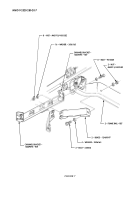
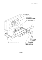
(12) Remove four nuts, lockwashers, screws, and two latches from pioneer tool stowage tray as shown
in figure 5. Discard lockwashers.
NOTE
Remove all burrs and sharp edges.
(13) Locate, mark, and remove two metal brackets flush with frame as shown in figure 5. Prime and
paint exposed surfaces. (Refer to TM 43-0139.)
b. Crossmember Reinforcement Installation.
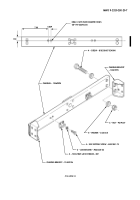
(1) In the event tool latch striker holes have not been added to channel 12469094, locate, mark, and drill
four 0.1495-inch (#25 drill bit) holes in channel as shown in figure 6. Tap holes to .190-24UNC-2B.
(2) Install 12469094 channel on 12469096 and 12469095 channel brackets with four B1821BH075C400N
screws, eight 2436168 washers, and four 9419507 nuts as shown in figure 6. Do not tighten nuts.
(3) Install two existing tool tray latch strikers on channel with four MS51851-75 self-tapping screws
and MS35338-43 lockwashers as shown in figure 6.
NOTE
It may be necessary to lift body from frame channel to
align holes and start bolts.
(4) Install channel brackets 12469096 and 12469095 on left and right frame rails with eight 9415560
bolts, sixteen 2436165 washers, and eight M45913/4-8CG8Z nuts as shown in figure 7.
(5) Install two 12469097 braces on left and right frame rails with two 455006 bolts, four 2436165
washers, and two M45913/4-8CG8Z nuts as shown in figure 7. Do not tighten nuts.
(6) Remove four nuts, eight washers, four screws, two support plates, backing plate, safety chain
plate, and two inner brace support brackets from rear frame channel as shown in figure 8.
Discard nuts, washers, screws, one support plate, locking plate, and two inner brace brackets.
(7) Install existing safety chain plate and support plate on channel with two braces 12469097, four
B1821BH050C400N screws, eight 2436165 washers, and four M45913/4-8CG8Z nuts as shown in
figure 9. Do not tighten nuts.
(8) Install towing pintle on channel with 7355396 washer and existing slotted nut and ensure washer
is positioned center on bumper and tighten slotted nut as shown in figure 9. Loosen slotted nut
slightly if towing pintle will not rotate easily.
(9) Align hole in towing pintle and slotted nut and install MS24665-628 cotter pin through slotted
nut and towing pintle as shown in figure 9.
(10) Tighten nuts installed in step 1 as shown in figure 6.
(11) Ensure both braces are on frame rails and channel and tighten nuts installed in steps 4 and 6 as
shown in figures 7 and 9.
MWO 9-2320-280-20-7
Change 1
5
Back to Top

