MWO-9-2330-390-25-1 - Page 32 of 54
MWO 9-2330-390-25-1
B-3
APPENDIX B.
MANEUVERING POSITION (Con’t).
b.
Removing Dolly Half From Maneuvering Position.
CAUTION
•
Use extreme caution to ensure that near (left side) top beam vertical tube does not
contact control valve and fittings an cause damage when removing dolly half from
maneuvering position.
Carefully follow all steps and monitor position of lift
cylinders and pivoting tray to guard against blinding and interference.
NOTE
•
The following steps are performed at the front and/or rear dolly as required.
When
procedure has been completed, bottom beam will be resting on ground with top
and bottom beams vertical.
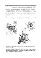
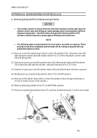
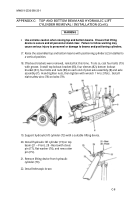
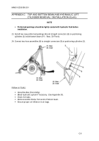
(1) Push up on two lift cylinder levers (56) to retract lift cylinders (73).
Stop when near (left
side) top beam vertical tube (58) reaches within ½ in. (13 mm) of hydraulic control valve
(74) and fittings (90).
(2) Continue to push up on two lift cylinder levers (56), allowing far (right side) lift cylinder
(73) to lead near (left side) lift cylinder.
Maintain clearance of ½ in. (13 mm).
(3) Continue to push up on two lift cylinder levers (56) until bottom beam (3) rests on ground.
(4) Quickly push up on positioning cylinders lever (71) to FLOAT position.
(5) Push up on lift cylinder levers (56) to retract lift cylinders (73) until approximately 6 in.
(15 cm) of stroke remain on lift cylinders.
(6) Return positioning cylinders lever (71) to NEUTRAL position.
(7) Push up on positioning cylinders lever (71) until top and bottom beams (1 and 3) are vertical.
Back to Top

