SMI-9-2320-387-14P-1 - Page 28 of 671
SMI 9-2320-387-14&P-1
2-6
Change 4
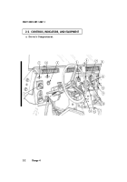
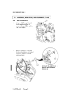
2-2. CONTROLS, INDICATORS, AND EQUIPMENT (Cont’d)
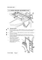
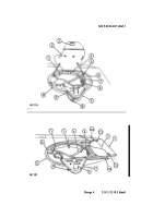
KEY
ITEM AND FUNCTION
1
Directional signal lever
activates turn signal lights.
2
Warning hazard control
activates the warning flashers.
3
Horn button
activates vehicle horn.
4
Baffle operating rods
slide open to allow heated air into crew compartment
and are controlled by the temperature control lever (can also be operated
manually from under the hood).
5
Fresh air intake lever
is pulled back to allow fresh air into crew compartment,
or pushed forward to close.
6
Simplified Test Equipment/Internal Combustion Engine-Reprogrammable
(STE/ICE-R) diagnostic connector
is attaching point for the Vehicle Test Meter
(VTM) to facilitate vehicle electrical and engine systems diagnoses.
7
Transmission indicator lamp
comes on when ignition switch is turned on, and
goes off when vehicle is started and is also used to flash diagnostic trouble
codes when Transmission Control Module (TCM) is placed in diagnostic mode.
8
Transmission shift lever
is used to select vehicle driving range, P (park),
R (reverse), N (neutral),
(overdrive), D (drive), 2 (second), and 1 (first).
9
Transfer case shift lever
is used to select vehicle driving range, H/L (high/lock
range), H (high range), N (neutral), and L (low range).
10
Transfer case indicator lamp
illuminates when transfer case has completed
the low-range shift and high/lock-range shift.
11
Parking brake lever
is used to apply parking brake. Safety release button
must be depressed to release parking brake.
12
Fording control switch
(M1113, M1151, and M1152) (deep water fording kit
only) allows operator to select VENT during normal operating conditions or
DEEP FORD for deep water fording.
13
Steering wheel lock cable
permits steering wheel to be locked to prevent
unauthorized use of vehicle.
D
Back to Top

