TB-9-2320-279-13-P-2 - Page 324 of 460
II106700-5
Rev. B
Page 60
4.
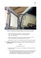
Adjust the Rear Side Cab Armor Panels with the Cab Entry Hand Hold, as
necessary to achieve the proper gap, and tighten the two locknuts.
5.
Mark the attachment points on the top and second bottom hole of the Rear Cab
Armor Panel using a center punch and a hammer (use the slotted holes in the
top and bottom of the Panel.
6.
Remove the Rear Cab Armor Panels.
7.
Using a drill and a 3/16-in. drill bit, drill pilot holes in the positions marked.
8.
Using a drill and a 17/32-in. drill bit, drill through the pilot holes into the cab.
b.
Install the Rear Cab Armor Panels onto the cab.
1.
Re-position the Cab Entry Hand Hold on the second hole from the top of the Rear
Side Cab Armor Panels and secure the Panels and the Aft Armor Panel plates
(P/N 113316) on the inside of the cab in place using two bolts
(7/16 x 14 x 4.000 LG), four flat washers (7/16 ID), and two locknuts (7/16 – 14).
Do not tighten the bolts and nuts at this time.
NOTE
As mentioned previously, the gap between the rear edge of the Armored Door
and the front edge of the Rear Side Cab Armor Panels should be 1/8 to 3/16 in.
wide.
2.
Verify that the gap between the rear edge of the Armored Door and the front edge
of the Rear Side Cab Armor Panels is 1/8 to 3/16 in. wide.
3.
Once the Rear Side Cab Armor Panels, with the Cab Entry Hand Hold, are
adjusted as necessary to achieve the proper gap, torque the four locknuts
(7/16 – 14) to 35 ft-lb.
c. Repeat Steps “a” and “b” for the Rear Side Cab Armor Panels on the other side of the
HEMTT cab.
5.1.9
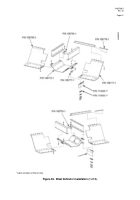
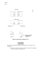
Install the Blast Deflectors, Kit P/N 106706-3 (see Figure 36)
NOTE
HEMTT Armor Kits manufactured after 2004 may include additional mine blast
components (Mine Blast Shield, P/N 111458-1, and Radius Block, P/N 11493-1).
All
assembly instructions are the same for kits with or without the additional components,
except as noted in Section 5.1.9, Item c, Step 9.
a.
Install the Driver’s-side (LH) Blast Deflector.
1.
Remove the drag link from the pitman arm on the steering box to gain access to
the fender supports.
Back to Top


