TB-9-2320-279-13-P-2 - Page 329 of 460
II106700-5
Rev. B
Page 65
6.
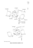
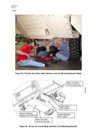
Using a suitable lifting device (forklift, jack, etc.) position the driver’s-side Blast
Deflector (P/N 106717-1) under the cab and secure the forward end to the bottom
of the lower brush guard frame using three Doubler Plates (P/N 106719-1),
three bolts (0.750 - 10 x 2.500 LG), six flat washers (0.750 ID), three locknuts
(0.750 – 10).
Install the locknuts finger tight at this time.
7.
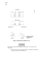
Install the Threaded Plate (P/N 106778-1) into the open end of the fender support
and align it with the previously drilled bolt holes.
8.
Install four bolts (1/2 – 13 x 1.500 LG) and four flat washers (1/2 ID) through the
rear of the driver’s-side Blast Deflector and the previously drilled holes in the
fender support and into the Nut Plate (P/N 106778-1) (see Figure 38).
Back to Top


